. (From simple to complex). -M.: "Crystal", 1998. - 208 p.
RADIO CONTROL ship models
TO HELP MARINE MODELERS
To help young ship modelers
ABOUT ORGANIZATION AND CONDUCT OF COMPETITIONS IN SHIPMADE SPORTS
Rules for competitions in ship modeling. -M.: TsMK DOSAAF, 1971.
FOREIGN PUBLICATIONS on ship modeling
- Khorkov V. High-speed sports model / Magazine “Military Knowledge” No. 1, 1959.
- Tsvirkunov V. High-speed sports model / Military Knowledge Magazine No. 6, 1959.
- Veselovsky A.I. Manufacturing and installation of propellers / Military Knowledge Magazine No. 8, 1960.
- Potapov G. Hydrostatic device for submarine models / Military Knowledge Magazine No. 8, 1962.
- Babkin I. How to make a mini-aquadrome / Military Knowledge Magazine No. 5, 1989, 26 p.
Some people have a strange, but very remarkable and colorful hobby. It is called assembling ship models from wood. What does it take to make such a beautiful thing? Creating a wooden model is not so easy. From this article you will learn how to create one out of wood with your own hands. We will also take a short excursion into history.
Francis Drake
Many history buffs know the name of the “Iron Pirate”; his homeland was England. He became the captain of a sailing ship at just 16 years of age. At first he was a ship's priest, and then a simple sailor. But his fame really exploded when he became a brave and very formidable pirate. In the 16th century, he made quite a few voyages and took part in a considerable number of battles.
Golden Hind
At the moment of dawn of fate, several sailing ships arrived on his property. His main flagship was the Pelican. This ship was a five-deck, three-masted ship. There were 20 artillery weapons on board. All kinds of maritime stories rarely tell us that a ship that already has a name can be renamed, but it was with the Pelican that, by the will of fate, such a story happened. In 1578, Francis Drake changed the name of this ship to "Golden Hind" (in Russian this name sounds like "Golden Hind"). It was under this second name that he was inscribed in sparkling golden letters in the world history of seafarers. Francis Drake performed quite a few breathtaking deeds on it, which were later recounted in history and adventure books.
It is such wonderful ships that make many people assemble wooden ship models with their own hands. Drawings of many similar designs can often be found on the Internet. So, inspired by the ancient history of navigation, we will learn from this article information on how to do something similar.
DIY wooden ship model: from beginning to rainbow horizons
In fact, the history of modeling consists of several stages. Moreover, each of these stages is associated with several characteristics. A miniature shipbuilding enthusiast may need to be able to modify available materials. It is also important to expand the choice of modeling objects. Once it has developed enough, then it can have mass production of models. The next stage will be the development of bench exhibition modeling from the kits that he already has. Subsequently, it can develop to the formation of individual segments. It can be anything - from ship models and in flesh to copies of individual motorcycles, trucks, as well as all sorts of other cars.

DIY wooden ship models: drawings, instructions, tools
So, well, let's start creating such a ship. Carving prefabricated wooden ship models is not the easiest task. You will need many tools for this. Among them are: a knife, a chisel, a hammer, a block (and, if necessary, a saw), thin cloth, superglue, a long wooden spike, a rope, a drill. In addition to this, you will need two more very important parameters. Firstly, it is time, and secondly, an important quality of those people who create prefabricated models of ships from wood is patience.
Carving of a ship from wood
First you have to work with a chisel. You should file everything plus remove the old bolts that have a flat head. It won't take you much time - just two minutes. In these two minutes, the pre-processed block will later become a boat. Now you need to clean the block. You should carefully scrape off the bark. Hold the block itself directly towards the tool. Let's take the standard design as an example for our small ship models, which we will build according to the principle below. Take a pencil and sketch a preliminary sketch on a block. After this, process the block with a sharp knife. The tilt of the blade itself should be at an angle of about 10 degrees. When planing, keep in mind that this is not the easiest job, so be patient. You should not forget that if for any reason you make a mistake, it will be quite difficult to correct everything. Remove the chips layer by layer, while you should try and process the original block as smoothly as possible. It is important that the top and bottom must be parallel.

Please note that you don't have to throw away the shavings at all. The fact is that, in principle, it can be used as an additional material as mulch.
Carving of the front and sides of the ship
Well, now we need to draw the front, bottom, and also the back. We will cut them out in exactly the same way as above. It is necessary to make these parts even. In order to get the bow of the ship, you will have to saw off a piece from the front. Following this, you should round off the cut using a knife. When you make the nose, try to tilt the knife blade itself back. It should be directed towards the stern.

Drilling holes and subsequent installation of equipment
You should have several spiers. Therefore, drill a number of holes; they should be slightly larger in size than the beams themselves. It is important that there are not too many holes. Otherwise, you may end up with a crack. And because of a crack, as we know, a serious disaster can occur - a leak. Don't use glue! If you do this, then further the work will pass with much greater difficulty.
Installing sails on the model
First, decide how many panels you want to have on your final ship. Let's take as a condition that we will have four panels for the first mast and the second, and three for the last. Following this, take several wooden spiers and cut them. Cut the fabric into a trapezoid shape. Then start gluing them together. Make notches on the branches of the sails, fasten each branch with a corresponding notch. Then glue the middle of the edges to the sails. Repeat the same for all masts. It is best if you build the rear mast first, then the middle one, and then the bow one.

Now let's start installing the upper flying sail. Cut out a kite shape from fabric. Take the thread and attach it to the opposite corner of the panel. Leave ends on both sides for all corners. Glue a small piece of thread onto the top of the boat. It should be slightly higher than the bow of the boat itself. Measure from the opposite corner to the middle of the lower branch of the sail on the front mast. Then cut off the thread that you measured and glue the tip to the appropriate place.

You should leave a few threads on each side. Pull them back and glue them straight inside the boat. Then you can cut off the excess rope. Create and attach the back panel in the same way. It should be attached to the back of the rear sail. Measure, cut, and make sure it fits the two tabs. Then glue them in the corners.

Well, now you have learned how to make simple wooden ship models. And although everything is described in this article only in general terms, we hope that it will help you in your future career as a “shipbuilder”. If, of course, you are interested in this. Believe me, this is a worthwhile activity!
When organizing a shipbuilding circle, the leader is faced with a problem: where to start? By introducing a new section, the editors set the task of facilitating the selection practical material for the work of modelers of the second year of study.
In the second year of classes, it is more expedient for most circle members to work using ready-made, worked-out drawings, and only the most prepared can be entrusted with making models of their own design. In this case, it is imperative to ensure that when developing a drawing of the model and its design, all the requirements for this class of models, set out either in the Regulations on exhibitions and competitions, or in the Unified All-Union Sports Classification of Models and the Rules for Competitions, are taken into account.
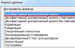
Today we provide drawings and a description of a river monitor with a rubber motor - the first of five models that were developed, built and tested in the ship modeling laboratory of the Moscow City Palace of Pioneers and Schoolchildren and recommended for clubs.
In the future, models of a dry cargo barge with an electric motor will be published on the pages of the magazine. missile boat with an electric motor, a river passenger ship with a rubber motor and a submarine with a rubber motor. All of them are easy to manufacture and have good shape, showed high performance and “fit” into ship modeling standards.

1 - railing, 2 - cabin door, 3 - lifebuoy, 4 - mast, 5 - running lights, 6 - bell, 7 - fire extinguisher, 8 - antenna, 9 - flagpole, 10 - steering wheel, 11 - propeller, 12 - bracket, 13 - skylight, 14 - hatch, 15 - fender beam, 16 - coaxial machine gun turret, 17 - load (lead), 18 - wave deflector, 19 - view, 20 - spire, 21 - anchor chain 22 - anchor, 23 - front rubber motor hook, 24 bale strips 25 forepeaks, 26 - bollards, 27 - universal turret, 28 - conning tower, 29 - distinctive lights, 30 - ventilation fungus. 31 - engine hood, 32 - boat, 33 - davit, 34 - smoke equipment
The peculiarity of the first four is the use in their design of the same, universal body, which is made by manual stamping (extrusion) from polystyrene sheet plastic. These models differ in their purpose, superstructure design and coloring. Effective items and chassis parts for them must be manufactured and installed on the body in accordance with the drawings of this model.
1. MANUFACTURING A PUNCH AND A DIE FOR STAMPING THE CASE. The punch is cut from a rectangular block of soft wood - linden, alder, aspen. The work is carried out on a carpentry workbench. The sides and deck are marked using cardboard templates, after which they process it, finally finish it with a file and sandpaper, and begin stamping the polystyrene hull.
The matrix is made of plywood with dimensions 600 X 250 X 5 mm. A punch is placed in the middle of the sheet, deck down, and traced with a pencil. Then an allowance for the thickness of the material is outlined, the contours are cut with a jigsaw, then processed with a file and sandpaper.
2. BODY. A piece of polystyrene or copolymer measuring 500 X 250 mm is heated in an oven or over an electric stove until it softens, placed on the punch and pressed with a matrix until the body takes the desired shape. Wipe the mold from above with a damp cloth, pressing the polystyrene against the punch.
3. PROPELLER INSTALLATION AND STEERING DEVICE FOR MODELS WITH RUBBER MOTOR. The propeller-motor group of such models consists of a rubber motor, front and rear brackets, a propeller and a steering wheel. To make a rubber engine, special rubber threads with a cross section of 1X1, 1X2, 1X4 mm are used. The length of the rubber motor in an untensioned state is about 400 mm with the number of threads from 16 to 24.
The rubber motor is assembled like this: two nails are driven into the board at a distance corresponding to its length. The rubber thread or tape is laid out evenly, without tension or loops. The ends are tied in a knot. So that the resulting skein can be put on a hook and attached to the propeller shaft, ears should be made, as shown in Fig. 11. You can secure them by wrapping them with thick thread.
The front bracket bends from steel wireØ 1.5-2 mm and is fixed in the bow of the body on a wooden boss.
The rear bracket is cut out of sheet metal or brass according to the drawing and attached to the bottom of the body. To do this, two holes are cut in the aft part of the bottom. The arms of the bracket are inserted there, unbent and pressed with small pieces of polystyrene and wood, coated with glue.
The screw is cut from a circle of tin or a ton of brass Ø 35-40 mm. The outer ends of the propeller blades are bent at 40-45°.
To install the screw in place, you need to insert a piece of wire Ø1-1.5 mm and 40 mm long into the hole in the rear bracket and solder the screw; the other end is bent in the form of a hook.
The steering device of the model is simple. The rudder blade is cut out of tin and attached to the body, as shown in the drawing, using a wooden boss.
4. PROPELLER INSTALLATION AND STEERING DEVICE FOR MODELS WITH ELECTRIC MOTORS. The propeller group consists of a motor and a drive shaft. The deadwood is a tube 110 mm long, with an outer Ø of 3-4 mm and an inner Ø of 2-3 mm. A three-bladed propeller Ø 25-30 mm is cut out of tin or thin brass with scissors. The screw shaft can be made from a knitting needle Ø 1.5-2 mm. The deadwood is attached to a pre-cut hole in the body using glue. The propeller shaft is connected to the micromotor with a piece of vinyl chloride tube 20 mm long or a soft spring.
The handlebars are cut out of tin, and both plates are soldered to a stock (wire rod). A boss is glued inside the body, in which the steering stock is secured.
5. MANUFACTURING A STAND (KILL BLOCK). The stand consists of two slats, fastened with posts cut from plywood 4-5 mm thick. The recess for the body is made according to the shape of the latter.
6. ADJUSTMENT AFLOAT. Testing the model consists of adjusting stability and creating the necessary draft. Lead ballast is used for this. The hull is placed on the water and the side and bow roll are checked. If, upon launch, the model goes to the left, then the rudders must be turned to the right, and vice versa, until the model goes straight ahead. By selecting the number of threads of the rubber motor, you can achieve maximum speed movements.
Monitors (sometimes called armored boats) are the most numerous class of warships in river flotillas. They are sufficiently seaworthy, so they can swim in large lakes and coastal areas.
The Monitor is a small ship, its displacement reaches 60 tons. The shallow draft makes it easier to navigate rivers. High speed (up to 14 knots) ensures swift fire strikes. To protect against artillery fire, the wheelhouse, deck and vital parts of the hull are armored.
We will build a monitor based on a universal housing, the production of which was just discussed.

The conning tower is installed in the middle of the deck. It can be made from a block of wood or polystyrene foam, or glued together from pieces of thin plywood (polystyrene, plexiglass, celluloid, cardboard).
Doors are hung on the side walls of the cabin and handrails made of thin wire of a multi-core electrical cord are installed. Behind the wheelhouse, an engine hood is glued onto the deck - a superstructure over the engine room. There is a skylight on it. It serves for daytime lighting and for ventilation of the engine room. Fan simulators are machined into lathe or sawed off from a round strip.
Entrance hatches and deck spaces are made of thin plywood or celluloid, plexiglass, and polystyrene. The hinges of the lids and handles are bent from thin wire.
The monitor's artillery armament consists of one 76 mm gun mounted in a turret in front of the conning tower, and four heavy machine guns in twin turret mounts. Gun turrets are made from a block of wood or foam plastic or stamped from polystyrene - just like the body.
The gun barrel can be turned on a lathe or cut from a wooden strip (pine, bamboo). The rail is rounded and cleaned with a file and sandpaper. A barbette is made under the tower - a disk made of plywood (cardboard, celluloid).
Machine gun barrels are thin nails or pins on which spirals of thin wire-vein are strung.
Equipment for setting up smoke screens is installed at the stern. These are wooden cylinders, placed three on each side on special wire holders.
Running (distinctive) lights are used to determine the direction of movement of the boat at night. On the sides of the cabin they install side lights: red on the left, green on the right. The remaining lights are attached to the mast.
The mooring device consists of bollards, views and bale strips. Bollard tubes are turned on a lathe or cut out. The base is made of plywood or celluloid. The view drums are machined from celluloid. The cheeks and cylinder are made from lath and wire. Side stands are made from celluloid (you can use cardboard or plywood). Then everything is glued together in accordance with the drawing.
A mast with a yard and a gaff is installed on the roof of the cabin. The mast parts (spar) are made of bamboo or pine slats, the locator is made of metal or plastic mesh.
Here's how life preservers are made. First, a wire is wound around the rod, then the resulting spiral is cut. They are painted by dipping half of them into jars of white and red paint.
Rails protect the deck of the boat along the side. Rail posts are pins driven into the deck. Thin strands of electrical wire are soldered to them or threads are glued.
The monitor is painted in three colors: the underwater part of the hull is green, red or black, the surface part - superstructures, hangars, masts, anti-aircraft guns, as well as deck parts and superstructures - ball (gray) color. The waterline is marked with white. You can also stick a thin line from a strip of celluloid, polystyrene, or whatman paper. The deck is covered with brown or dark green paint. The anchor device is painted black.
Ship modeling is one of the technical sports. Well-established work in a circle allows children to develop a love of work, educate them in the spirit of collectivism, instills determination, attentiveness, develops independence, creative design thinking, and helps them master various work skills. By engaging in ship modeling, students consolidate and deepen the knowledge acquired in physics, mathematics, and drawing lessons, and learn to apply them in practice. Thus, ship modeling helps expand the polytechnic horizons of students.
Ship modeling classes in a circle are one of the forms of disseminating knowledge on the basics of maritime affairs among students and cultivating their interest in maritime specialties. This is very important, since our country is a maritime power.
Civil and Navy Having ships at their disposal, they need highly educated, skilled and knowledgeable specialists in maritime affairs.
Work practice shows that the knowledge and skills acquired in the circle greatly help children during their service in the navy; many members of the circle are given guidance in choosing a profession.
The main form of summing up the work of the circle is the participation of its members in public events: competitions, exhibitions, demonstrations, etc.
One of the features of the circles working today is that the material base is close to zero and the models made by the guys are mostly simple. Therefore, competitions in clubs of the first and second years of study are not final in nature, but serve as one of the forms of conducting classes.
(Quote from a forgotten source).
What are these simplest models for first-year study circle students? 
The development was based on an article in the magazine "Modeler-Constructor".
Have you ever built a yacht before?
But it’s not difficult at all! Let's try to build it together. Just carefully read everything that is written here, and take your time when you start working.
Just like in a real shipyard, our first task is to select the material. To build a yacht, you and I will need: a 10-30mm thick plank for the hull, 4mm plywood for the keel, deckhouse and keel block, a 6x6mm batten for the mast and keel block, film for the sails, thread, a pair of stationery pins, a small piece of sandpaper, glue PVA, narrow tape, gouache or tempera paint, PF parquet varnish, Oracal film for the waterline and numbers. You also need the simplest tool: a jigsaw with files, a sharp knife with a retractable blade, pliers, a brush and scissors.
Now let's get to work. First, we cut out the deck (hull), parts of the keel block (stand), deckhouse and keel with an allowance of 1-2mm. Using a sander (a block with sandpaper), remove the allowance so that the lines of the parts remain. Using a knife from the underside of the deck, select a groove 3-4mm deep under the keel. Take the mast blank and use a sander to round off the edges. We drilled a hole in the deck for the mast. Glue the mast and keel to the deck at exactly right angles. Glue the cutting. Glue the keel block. Coat the model and stand with varnish 1-2 times and dry thoroughly. Lightly sand surfaces to remove lint. Paint the model and varnish again. Each layer of paint and varnish must be thin, without smudges and completely dry. According to the drawing, secure it with pins on the deck. Now pull the forestay strings and attach the sails (mainsail and staysail) to them with narrow strips of tape. Glue the waterline and numbers.
That's it. Now the model can be run.


I bring to your attention contour models of rubber-powered ships. The models are simple in design, very technologically advanced in production and are distinguished by high driving performance. The development was based on kits previously produced by the USSR DOSAAF system.
Sets of materials produced in the old days of the Fregat preschool educational institution for the construction of contour ship models were intended for children's technical creativity and were designed for children of secondary school age with initial modeling experience. The set consisted of parts, blanks and materials from which you can build a working sports boat model.
The model can be used to participate in ship modeling competitions of various ranks, as well as to organize leisure time for fans of this sport.
When starting to build a sports model, carefully read the description, drawing and assembly diagrams.
While working, strictly follow the safety rules!
Using a jigsaw, we cut out the body of the model from a plank 10-20 mm thick. When sawing, a small allowance is left, which is sanded off with a file and a “grinder”. Remove the allowance so that the contour lines remain. Sand all edges thoroughly.
Using a jigsaw, we cut out the outline of the model from plywood 3-4 mm thick and process it in the same way. Using a sharp knife, select a 4 mm deep groove in the body and glue the outline into it. On the bottom of the model, glue a keel 15-20 mm high from the contour material.
Coat the contour and body of the model with varnish and dry thoroughly. Lightly sand the model to remove lint.
The propeller shaft bracket and rudder are cut out of sheet metal with a thickness of at least 0.5 mm. The casing is a metal tube of suitable diameter. The bow bracket is a self-tapping screw. Shaft - screw with M3 thread. The ring on the shaft is bent from a paper clip.
Bend the propeller shaft bracket and solder the casing to it. Secure the bracket to the bottom of the model with self-tapping screws. Solder the ring for the rubber motor to the shaft. Insert the propeller shaft into the housing and place the washer on the shaft. Clamp the propeller between two nuts on the propeller shaft. Secure the nose bracket (self-tapping screw). Secure the steering wheel with self-tapping screws to the bottom of the model. Make sure that both brackets and the steering wheel are located strictly along the centerline of the model. Bend the propeller blades to one side at an angle of 20-30 degrees. Make sure that the propeller blades do not touch the rudder and the hull of the model.
Paint the assembled model with TEMPERA paints and cover it with parquet varnish. Each layer of paint and varnish must be thin, without smudges and completely dry.
Cut out the waterline from Oracal and paste it on.
Lay the rubber thread in a straight line on the surface of the table. Use a ruler to measure the distance between the bow bracket and the ring on the propeller shaft. After measuring five distances on the rubber thread, cut off the rubber motor blank. Tie the ends of the segment together with a tight double knot. Thread the resulting loop into the ring on the propeller shaft to the middle, and both ends of the loop onto a paper clip and then onto the bow bracket.
A correctly built and adjusted model should cover a distance of 8-10 meters. By increasing the number of threads and the length of the rubber motor, the distance traveled by the model will increase. It is better to start the rubber motor with two people as follows. Remove the end of the rubber motor from the nose bracket, put the end of the rubber motor on the wire hook inserted into the drill. Pull out the rubber motor so that its length is 1.5-2 times longer. Keeping the rubber motor taut and not allowing the propeller shaft to rotate, make 100 revolutions with the drill, gradually shortening the length of the rubber motor. After winding, put the end of the rubber motor on the bow bracket and, holding the propeller with your hand, place the model on the water. Release the propeller and launch the model. If the model does not walk straight, turn the steering wheel in the opposite direction to which the model is turning.
Only run the model under adult supervision.
When starting the model, do not touch the rotating propeller.
Do not run the model in a human bathing area. While in the water area, follow the rules for being on the water. 


The body of the model is planed from a 20mm thick board. Keel - strip dimensions 500x20x5mm. On the deck it is necessary to mark with a pencil the places where the parts will be installed. Achieve symmetry of the markings when viewed from above. The breakwater and side are made of veneer, cardboard or thin plywood. Cargo deck fencing - slats with a section of 10x3mm. The cockpit, wheelhouse, engine room and fuel tank are solid blocks (a cardboard version is possible). Guy rod, whip antenna and flag rod - wire with a diameter of 2 mm (these parts are glued into pre-drilled holes using epoxy only). The exhaust pipe is a tube with an outer diameter of 3mm. Fuel tank neck - aluminum rivet. The base of the bollards is a rail with dimensions 10x8x1mm, the heads of the bollards are screws of a suitable size with slots filled with epoxy. The wooden parts are glued with good PVA glue. All seams and crevices between parts spill epoxy resin. Sand the entire model thoroughly with sandpaper. Coat the model 3-5 times with parquet varnish, drying each layer. Lightly sand the model to remove lint.
Paint the assembled model with TEMPERA. Each layer of paint and varnish must be thin, without smudges and completely dry.
We obtain the porthole rings by winding aluminum wire onto a drill of a suitable diameter. Porthole glass, waterline and flag - ORACAL.
The chassis in design and installation methods is identical to that used in the construction of contour ship models with a rubber motor.
Since the center of mass of the model is shifted to the stern, it is necessary to place the cargo on the cargo deck closer to the bow of the model. This will eliminate the trim of the model. But what kind of cargo and what mass is up to the master shipbuilder himself to decide.
It should be noted that the model can be built with either a rubber motor or an electric motor.


The development was based on an article in the magazine "Model Designer" No. 5 - 1970
This model of a submarine can be built in two or three classes in a circle, and then launched all summer. By making several of these boats, you will be able to hold a number of interesting competitions.
“Rusalka” - that’s what we called this model - is equipped with one or two open-type rubber engines, that is, located outside. A boat with one engine is easier to manufacture, with two it is more difficult, but it sails better on a given course.
The body of the model can be made from dry spruce or pine boards 30 mm thick. Attach a 4 mm thick metal rod (ballast keel) to the bottom of it. Place a lead weight on it, the weight of which must be selected experimentally after all the mechanisms are installed in place and the body is finished, painted and varnished. A hook for the rubber motor is embedded in the front pylon, and a hole for the propeller shaft is drilled in the rear pylon. The undercarriage parts are similar to those on contour ship models.
Horizontal handlebars are cut out of galvanized metal 0.5 mm thick and fastened in pairs with self-tapping screws in the places indicated in the drawing. The vertical rudder is mounted on the rear pylon in the same way. Having completed all these operations, the boat hull is carefully painted and varnished.
When the paint and varnish have dried well, you can launch the “Mermaid” into the water. First, a weight of the required weight is selected. By gradually adding pieces of lead, you need to ensure that the boat (with a rubber motor!) floats on an even keel, sinking to the waterline. To do this, the load will have to be moved along the pin in one direction or another.
Having found the correct position of the weight, secure it with glue, start the rubber motor and try to start the Mermaid. It is very possible that she will not want to dive on the first voyage. Then use pliers to bend the rear edge of the front horizontal rudders slightly up and repeat the start. If this is not enough, slightly move the adjusting weight forward along the pin (do not forget to secure it again in the new position!).
A correctly adjusted model should dive, swim several meters underwater and, after spinning the rubber motor, rise to the surface.
“Rusalka”, equipped with one rubber motor, will turn to the side - due to the reaction of the propeller. To prevent this from happening, bend the vertical steering wheel slightly in the opposite direction.
With two rubber motors and propellers rotating in different directions, the submarine will not turn around. In addition, a twin-engine boat will have significantly greater speed and range.
We recommend!


Pavel comments:
Of course, everything is well described, screenshots of 3D models of ships broken down by materials and photographs of the finished ones... And where did the drawings and files of the 3D models go???
Quite unexpectedly, I saw in one newsstand the first issue (as it turned out - widely advertised on television!) of the next project of the Deagostini publishing house - "Great Sailboats". Everyone was offered construction within (attention!) - two years a fairly reliable copy of one of the famous sailing ships - the galleon "San Giovanni Batista".
The fact that the very first advertising issue of this magazine with the very initial set of REAL parts of the future model caught my eye seemed to Dreamer to be a kind of good omen. Although, to be honest, even the recommended selling price for the first issue, multiplied by 100, was not I came across as TOO modest... But let's not talk about sad things!
Despite the fact that from the place of the happy (or maybe fatal?) purchase to my house is a couple of hundred meters, this path has never seemed so long! My soul was literally bursting with the desire to open the package, look inside and, most importantly, start assembling!!! Apparently, the construction of “a certain number” of REAL sailing yachts What do visitors to the project mean? PhotoDreamStudio can read this site. Here I will post material related to this new hobby of mine - ship modeling.
By the way, on the way home, as it turned out later, a very wonderful idea occurred to me - along with assembling a real model of a sailboat, make a “virtual” copy of it on a computer.
So, the first set of parts has been unpacked, the MOST DETAILED assembly instructions, illustrated with magnificent color photographs, have been studied...
Before gluing began, all parts included in the delivery kit were carefully measured and scanned for subsequent modeling in the 3D computer graphics program 3D Max. I don’t know how everything will work out in the future, but for now I intend to accurately reproduce on the computer all the parts from which the model is assembled - including hull structural elements, slats for lining the sides, sailing parts, etc.

Upon completion of the work provided for in the fourth issue of the magazine "Great Sailboats", the final design acquired a more or less "showable to guests" appearance - an idea began to form, if not about the appearance, then at least about the dimensions of the future ship. Connecting to 3D Max with the famous DreamScape plugin and the first steps in texturing details also contributed to the expressiveness of the rendered image.

All these vicissitudes of real and computer shipbuilding did not go unnoticed by my students at Children's Art School No. 2, where I teach computer graphics. The desire to model something like this in 3D has taken possession of some, apparently, the most fragile children's minds! I had to urgently find more or less intelligible drawings of the ships on the Internet (can’t wait two years until all the details of the San Giovanni Batista are purchased and scanned?!)
As a result, several sailing ships were laid down on virtual slipways, in particular, one of the “trinity” of Christopher Columbus - the caravel "Pinta" and the flagship of the famous corsair and navigator Francis Drake - the galleon "Golden Hind".


It should be noted that the very idea of creating a three-dimensional model of a sailboat turned out to be very beneficial in methodological terms. The variety of object forms of the ship opens up wide opportunities in mastering various techniques modeling. And in combination with texturing, creating a realistic environment - water and sky, we can safely say that the sailboat is almost ideal educational project for 3D computer graphics!


On at the moment The greatest difficulty was caused by the sheathing. For comparatively short term several alternative options were tried until the choice settled on the optimal one, as it seems to me, from the point of view of a combination of labor intensity and reliability appearance: sections of “sheathing boards” are placed on the side surface of each frame. Then all splines belonging to one “board” are combined (Attach), and a three-dimensional surface is built on their basis (modifiers Cross Section, and then Surface). After assigning materials, additional coordinate reference of the texture maps used (UVW Mapping) will be required.
Of course, none of the images presented here claim to be of any artistic quality or even completeness. All this is a working process that still goes on and on...
As kit parts were added to the real model, the need for a comfortable organization of the assembly process gradually became apparent. In particular, it is quite obvious that installation of frames on the keel is best done on some kind of slipway - the so-called. work stand. I would like to note with pleasure that the stand design I independently came up with turned out to be practically a twin of the one shown in the educational film on assembling a sailboat attached to the second issue! It's a small thing, but it's nice!
Along the way, we managed to select paint and varnish materials that were suitable in color and type. Now all the parts, as described in the manual, before assembly are carefully sanded with fine sandpaper, tinted with stain of different colors ("oak" - for frames and "pine" - for decks, which, after gluing the flooring from 5 mm strips of the finest veneer, are covered twice with artistic acrylic varnish.). A month and a half is behind...


It is with great pleasure and even (I won’t hide it!) with some pride that I publish this composition literally yesterday “baked” on a shipbuilding theme. The author is one of the students of Children's Art School No. 2 Ilya Lushnikov.
By the way, Ilya came to our computer class in mid-January 2010, and before that he had never worked in 3D graphics at all. These are the students in our Art School!

Nostalgie... I will not hide that what first of all prompted me to start assembling the “San Giovanni Batista” model was nostalgia for the times when my introduction to the world of sails had just begun. And our first family yacht was the trimaran "Allegro" - a rebuilt rowing boat "Mullet", equipped for stability with retractable beams with foam floats and two sprint sails.


It was at Alfer’s suggestion that I, who had never picked up anything heavier than a landing craft, in a relatively short period of time built a completely comfortable and seaworthy compromise, Theophilus North, based on a design taken from the Boats and Yachts magazine.
Alfer and I worked in the same organization at that time. However, before that, too, in the department of the chief architect of KamAZ, from where they quit almost at the same time, but for various reasons. And they met again in the KamAZ Young Technician Club, where Alfer created a phenomenon that was most interesting in every sense - the Children and Youth Shipyard. Well, your humble servant “accompanied by the roar of a circular saw from the next office” taught schoolchildren the basics of design. And, in particular, he also taught a rather interesting course of his own, “layout from paper and cardboard,” built mainly on the production of various puzzles.


As an illustration, I will say that the final work of fifth- and sixth-graders after the end of the second year of study was an ACTUAL model of a Rubik's cube, consisting exclusively of paper and glue! And in addition, there were large-scale models of sailing yachts (how could we live without them?!), the Nikolai Ostrovsky tank for the museum of a Chelny school, all kinds of decorative compositions, boxes with a combination lock, and so on. Truly, the possibilities of paper are endless, as I could see while still studying at the Sverdlovsk Architectural Institute.


And so fate would have it, that when Alfer Yagudin left the Club a couple of years later, it was completely logical for me to take his place and continue the work he had started. In addition, my “puzzlers” somehow unexpectedly grew up and, instead of making paper boats and boxes with secrets, they began to seriously think about the endless expanses of Kama...


And so, the very next year we safely and with great fanfare launched our cruising 6-meter catamaran, all the hull parts of which were manufactured on a turnkey basis on the third floor of the residential building 25/12, where the Youth Club was located at that time KamAZ equipment...

All summer we went on multi-day hikes, experienced storms, suffered from boredom in the calm, repaired “on the fly” after unexpected breakdowns, swam, chattered our teeth from the cold in bad weather... But that’s a completely different story...


On the first day of spring, the mood is frankly yachting. In the sense that it is already convincingly felt that the next navigation is just around the corner... And therefore I decided to please (or vice versa!) the visitors of the project PhotoDreamStudio a story about how I designed and built my trimaran "Pun".
First, a little theory.
Every boatbuilder knows that when building a boat, two types of drawings are used: theoretical and structural. The theoretical describes the external geometry of the housing. To do this, imaginary (and therefore called theoretical) sections are drawn across the entire length of the boat at equal intervals, called spacing, and coordinates are given for all hull lines on these sections - height from the so-called. The main horizontal plane (OP), and half-latitude - the distance from the central Diametrical Plane (DP). All these numbers are summarized in one Plasma Ordinate Table, which is the basis for the actual design of the vessel.
And then the fun begins! The placement of actual frames, bulkheads, and indeed all structural elements of the vessel, as a rule, is subject to various “external requirements”, primarily the tasks of ensuring seaworthiness, strength, general layout, layout of the main elements of equipment, ergonomics, etc. And therefore the problem arises of obtaining the exact dimensions of the hull section not in the place where some theoretical frame passes, but, say, 200 millimeters aft of it.
For this purpose, shipbuilders of “all times and peoples” use the so-called plaza - a drawing of the ship in NATURE size, or, in extreme cases, on a very large scale. On it, first, with the help of flexible slats and other devices, all the lines of the theoretical drawing are drawn, and then, as accurate as possible, the dimensions are taken in the places where the real frames are installed. If you are planning to build, say, a 9-meter cruising yacht, and for design you have, even with a creaking heart, the “hall” of an ordinary panel high-rise building vacated for you by your household, then this method is simply created for you! Shyutka.
Well, the author of these lines, who was then not a Dreamer, but the simplest Soviet Dreamer, since he had no idea about the Internet, and even knew about computers only that they were “very big,” went, as the FOUNDER bequeathed, to others through. I delved into the literature, revived the strong mathematical education I had once received (they say it was one of the best in the Union) (at one time I had the opportunity to study a little at one COMPLEX military school...), and as a result, showed it to the world and even published it in the mentioned one. previously in the magazine "Boats and Yachts" a method for designing the hulls of small ships based on the Lagrange interpolation polynomial (There is a five-minute silent pause in the hall. Everyone stands up...)

I will not bore the reader with boring details. I will only note that the smoothness of all lines, without local deflections (and for ride quality vessel (this is one of the main requirements) is controlled in my method through the study of derivatives. In addition, the method allows you to calculate changes in the dimensions of the frame taking into account the thickness of the material from which it will be made, that is, immediately include the so-called in the project. malku. I implemented this method on a regular calculator. By the way, the opinion of the magazine’s editors was that despite the novelty and originality, practical application it is difficult due to the high complexity of calculations. The irony of fate is that while the publication was being prepared, I quite unexpectedly acquired a then popular programmable calculator and, thanks to it, a complete calculation of the hull of a ship with any reasonable spacing began to take only a few hours! But that was LATER... But there’s no need to get ahead of your time, that’s it!


Everyone who saw our “team of professionals” unanimously told me: this idea is doomed to failure, because “they don’t build yachts with a kindergarten!” To which I replied, “I’m building a yacht for a family, and therefore I will do it with my family. What’s important is the process itself, that we do it TOGETHER.” Who was right - judge for yourself!


And at the end of this block, which also turned out to be somewhat nostalgic, I am publishing several computer pictures to give an idea of what we “built and built, and finally built!”


The last of the images presented here belongs to the “new” time - the other day, during classes at Khudozhka, we studied DreamScape with children, with all that it implies...


Well, for those who are not impressed by computer-virtual pictures, I suggest visiting the gallery of our website, dedicated to REAL ones on our REAL yacht!
First of all, congratulations to all visitors to the project PhotoDreamStudio Happy March 8th! On this spring day I wish you happiness, beauty, and all the best!

In anticipation of the 7th issue, ship modeling work was mainly carried out in the virtual space. To match the real one, a working stand was made, and texturing of the deck was continued.


After a number of attempts, which were considered somewhat unsuccessful by professional ship modellers on the forum dedicated to the assembly of this model, the final (hopefully!) version of the deck flooring was developed and translated into 3D.


The deck work coincided with a visit to our shipyard by a commission from the Ministry of Virtual Shipbuilding. We walked around and climbed everywhere...


Brief results of the inspection:
1. The scale of the structure is impressive.
2. No safety violations were identified. Almost.
After discussing the presented pictures on the mentioned forum, large-scale adjustments were made to the created model. The main starting point was that, as it became known from informed circles, the model of our sailing ship is being made on a scale of 1:50 in relation to the real ship.
In the images below, the Man in the Yellow Helmet and the construction site itself against the background of a modern multi-story building are depicted in relative sizes more or less close to reality.


And when assembling the real model, the first problems began to appear. WITH great surprise and with disappointment I discovered serious discrepancies in the sizes of the next batch of frames, in particular, the levels of the below-deck beams “dance” greatly. Despite the Publisher's repeated assurances, further shipbuilding work will be carried out with the most active use of files, hacksaws and other carpentry tools. And this is provided that all supplied parts are designed on a computer and cut by laser! Damn high technology...

The work provided for in the 7th issue was completed late at night. In the light of the dying fires, the traditional “memory” photography took place.


The virtual builder didn’t stand out with his final picture either...

We are waiting for the 8th issue!