SHAFTS and AXLES PURPOSE Shafts and axles are designed to guide and support rotating parts in space (gears, pulleys, blocks, sprockets, etc.). They differ from each other in terms of working conditions. The AXLE does not transmit torque and only works on bending. It can be rotating or stationary. The SHAFT always rotates and always transmits torque, works mainly on bending and torsion. Some shafts do not support rotating parts and only work in torsion. For example, car drive shafts, flexible shafts in power tool drives, etc.
 AXIS Design of a unit with a rotating axis: Design of a unit with a fixed axis: 1 – running wheel; 2 – key; 3 – axis; 4 – tapered roller bearings 1 – rope block; 2 – axis; 3 – locking strips; 4 – block holder

 DESIGNS OF WALKING WHEELS OF CRANES b a a – on a fixed axis: 1 – wheel; 2 – axis; 3 – gear b – on a rotating axis
 SHAFT The mechanism of movement of the crane with a low-speed transmission shaft: 1 – electric motor; 2 – coupling; 3 – gearbox; 4 – transmission shaft; 5 – brake. Cardan shaft Gearbox shaft
 CLASSIFICATION OF SHAFTS According to the shape of the cross sections of the shafts a – cylindrical solid b – cylindrical hollow c – with a keyway d – with splined grooves d – profile
 By purpose Ø Gear shafts – bearing gears, pulleys, sprockets and other parts. Ø Main shafts - in addition to gear parts, also carry working parts of machines or tools (turbine disks, chucks of lathes and boring machines, etc.) According to the shape of the geometric axis Ø Straight Ø Crankshafts - used not only for transmitting rotating torque, but also for converting reciprocating motion in rotational Ø Flexible, with a variable shape of the geometric axis. They are used in drives, instruments, dental drills, etc.

 SUPPORTING AREAS OF SHAFT Shaft 1 has a large number of supports called bearings 2. The part of the shaft covered by the support is called a journal. The end journals are called tenons 3, and the intermediate journals 4.


 REQUIREMENTS FOR MATERIALS FOR MANUFACTURING SHAFT ü High strength characteristics. ü Low sensitivity to stress concentration ü Ability to be subjected to thermal and chemical-thermal treatment ü Good machinability
 MATERIALS AND HEAT TREATMENT OF SHAFTS Purpose of the shaft Steel grade Type of heat treatment Lightly loaded shafts and axles, the diameters of which are mainly determined by rigidity Carbon steels: St. 3, Art. 4, Art. 5 Without heat treatment Shafts and axles with increased requirements for the load-bearing capacity of splines and axles Medium carbon and alloy steels: 35, 40, 45, 40 X, 40 N, etc. Improvement to hardness H = 250... 320 HB Shafts and axes with the requirement of high wear resistance : - sliding supports; - gear shaft Low-carbon structural steels: - quality 15, 20; - alloyed 15 Х, 20 Х, 18 ХГТ, 12 ХНЗА, etc. Cementation and hardening to hardness Н=58... 63 НRc Heavily loaded shafts Alloy steels: 40 ХНМА, 18 ХГТ, 38 Х 2 МУА, etc.
 TYPES OF DAMAGE TO SHAFTS Breakage of shafts in the zone of stress concentrations. They arise due to a decrease in fatigue strength due to the action of alternating stresses. Reasons: incorrect choice of structural shape of parts (fillet), violation of manufacturing technology (cuts, processing marks, etc.), violation of technical operation standards (incorrect adjustment of bearings, reduction of required clearances). Most often, breakdowns occur in the area where stress concentrators are located (keyways, fillets, holes, press fittings, etc.). Compression of working surfaces (grooves, keys, splines, wear of splines in moving joints and other types of surface damage). Frictional corrosion and pressure concentration in areas located near the ends of the hub (preconditions arise for the occurrence of sources of fatigue failure. Insufficient rigidity of shafts and axles for bending and torsion. Destruction due to transverse or torsional vibrations.
 SHAFT PERFORMANCE CRITERIA Strength Rigidity Vibration resistance Wear resistance The main criterion for the performance of low-speed shafts is static strength


 SUPPORT POINTS OF THE SHAFT a – on a radial bearing; b – on an angular contact bearing; c – on two bearings in one support; g – on a plain bearing
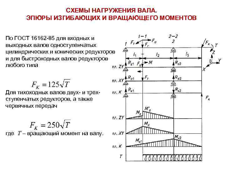 SHAFT LOADING DIAGRAMS. DIAGRAMS OF BENDING AND TORQUE MOMENTS According to GOST 16162-85 for input and output shafts of single-stage spur and bevel gearboxes and for high-speed shafts of gearboxes of any type For low-speed shafts of two- and three-stage gearboxes, as well as worm gears where T is the torque on the shaft.
 PROCEDURE FOR CALCULATING SHAFTS FOR STATIC STRENGTH Draw up a calculation diagram Determine the reactions of supports in the horizontal and vertical planes Build bending moment diagrams and torque diagrams Geometrically sum up the moments For dangerous sections (where the largest total moments are), calculate the diameters and finally develop the shaft design. Since the shafts operate under conditions of bending and torsion, and the stresses from axial forces are small, the equivalent stress at the point of the outer fiber, according to the energy theory of strength, is determined by the formula where; - design stresses for bending and torsion - axial and polar moments of the shaft section
 CALCULATION OF SHAFT FOR FATIGUE STRENGTH Performed as a test in the form of determining safety factors where S, S are safety factors, respectively, for bending and torsion stresses; [s] = 2… 2.5 - permissible safety factor. where σ-1, -1 are the endurance limits of the material during bending and torsion; K D, K D - stress concentration coefficients, taking into account the influence of all factors on fatigue resistance; σa, a - stress amplitudes; , - coefficients characterizing the sensitivity of the material to the asymmetry of the stress cycle; σm, m are the constant components of the stress change cycle.
 NATURE OF STRESS CHANGES IN SHAFT Symmetrical stress cycle Zero stress cycle Loads that are constant in magnitude and direction cause alternating bending stresses in rotating shafts, varying in a symmetrical cycle with amplitude σа and average stress σm Changes in torsional stresses in calculations are taken according to the zero cycle
Shafts and axles
PLAN LECTIONS
Materials and processing of shafts and axles.
Criteria for performance and calculation of shafts and axes.
Calculations of shafts and axes.
General information
Shafts- these are parts that serve to transmit torque along their axis and hold other parts located on them (wheels, pulleys, sprockets and other rotating machine parts) and perceive the acting forces.
Axles- these are parts that only hold the parts installed on them and perceive the forces acting on these parts (the axle does not transmit useful torque).
Classification of shafts and axles
Valov's classification groups the latter according to a number of characteristics: by purpose, by cross-sectional shape, by the shape of the geometric axis, by the external outline of the cross-section, by relative rotation speed and by location at the node .
By purpose they are distinguished:
gear shafts, on which wheels, pulleys, sprockets, couplings, bearings and other gear parts are installed. In Fig. eleven, A The transmission shaft is shown in Fig. eleven, b– transmission shaft;
main shafts(Fig. 11.2 - machine spindle), on which not only gear parts are installed, but also the working parts of the machine (connecting rods, turbine disks, etc.).
The following are made according to the cross-sectional shape:
solid shafts;
hollow shafts provide weight reduction or placement inside another part. In large-scale production, hollow welded shafts made from wound tape are used.
According to the shape of the geometric axis they produce:
straight shafts:
A) constant diameter(Fig. 11.3). Such shafts are less labor-intensive to manufacture and create less stress concentration;
b) stepped(Fig. 11.4). Based on the strength condition, it is advisable to design shafts of variable cross-section, approaching in shape to bodies of equal resistance. The stepped shape is convenient for manufacturing and assembly; the ledges can absorb large axial forces;
V) with flanges. Long shafts are composite, connected by flanges;
G) with cut gears(gear shaft);
crankshafts(Fig. 11.5) in crank gears they serve to convert rotational motion into reciprocating motion or vice versa;
flexible shafts(Fig. 11.6), which are multi-lead torsion springs twisted from wires, are used to transmit torque between machine components that change their relative position in operation (portable tools, tachometer, dental drills, etc.).
According to the external outline of the cross section, the shafts are:
smooth;
keyed;
splined;
profile;
eccentric.
According to the relative speed of rotation and location in the unit (gearbox), shafts are produced:
high-speed And input (leading)(pos. 1 rice. 11.7);
medium speed And intermediate(pos. 2 rice. 11.7);
slow-moving And weekend (slave)(pos. 3 rice. 11.7).


Rice. 11.2 Fig. 11.3


| |
|||||
| |
|||||
| |
|||||


Rice. 11.7 Fig. 11.8
Classification. The axes can be stationary (Fig. 11.8) or rotating together with the parts mounted on them. Rotating axes provide Better conditions The work of stationary bearings is cheaper, but requires the integration of bearings into parts rotating on axes.
Designs of shafts and axles. The most common is the stepped shaft shape. Parts are most often secured to shafts with prismatic keys (GOST 23360–78, GOST 10748–79), straight-sided splines (GOST 1139–80) or involute splines (GOST 6033–80) or fits with guaranteed interference. The supporting parts of the shafts and axles are called axles. The intermediate axles are called necks, the end axles are called tenons. The supporting areas that take the axial load are called heels. Thrust bearings serve as supports for the heels.
In Fig. 11.9 shows the structural elements of the shafts, where 1 – prismatic key, 2 – splines, 3 – axle, 4 – heel, 5 – cylindrical surface, 6 – conical surface, 7 – ledge, 8 - shoulder, 9 – groove for the stop ring, 10 – threaded section, 11 – fillet, 12 – groove, 13 – chamfer, 14 – center hole.
The journals of shafts and axles operating in rolling bearings are almost always cylindrical, and in plain bearings they are cylindrical, conical or spherical (Fig. 11.10.)
The main application is cylindrical journals (Fig. 11.10, A, b) as simpler ones. Conical journals with small taper (Fig. 11.10, V) are used to regulate the clearance in bearings and sometimes for axial fixation of the shaft. Spherical journals (Fig. 11.10, G) due to the difficulty of their manufacture, they are used when it is necessary to compensate for significant angular displacements of the shaft axis.


a B C D
Landing surfaces under the hubs of various parts (according to GOST 6536–69 from the normal series), mounted on the shaft, and the end sections of the shafts are made cylindrical (pos. 5 rice. 11.9, GOST 12080–72) or conical (pos. 6 rice. 1.9, GOST 12081–72). Conical surfaces are used to ensure quick release and a given tension, increasing the accuracy of centering of parts.
For axial fixation of parts and the shaft itself, use ledges(pos. 7 rice. 11.9) and shoulders shaft (pos. 8 rice. 11.9, GOST 20226–74), conical sections of the shaft, retaining rings(pos. 9 rice. 11.9, GOST 13940–86, GOST 13942–86) and threaded sections (pos. 10 rice. 11.9) under nuts(GOST 11871–80).
Transitional areas from one section of the shaft to another and the ends of the shafts are made with grooves(pos. 12 rice. 11.9, fig. 11.11, GOST 8820–69), chamfered(pos. 13 rice. 11.9, GOST 10948–65) and fillets. Radius R fillets of constant radius (Fig. 11.11, A) choose less than the radius of curvature or the radial size of the chamfer of the mounted parts. It is desirable that the radius of curvature in highly stressed shafts be greater than or equal to 0.1 d. It is recommended to take fillet radii as large as possible to reduce load concentration. When the radius of the fillet is severely limited by the radius of the rounding of the edges of the mounted parts, spacer rings are installed. Fillets of a special elliptical shape and with an undercut or, more often, fillets outlined by two radii of curvature (Fig. 11.11, b), used when transitioning fillets to a step of smaller diameter (makes it possible to increase the radius in the transition zone).
Application of grooves (Fig. 11.11, V) can be recommended for non-critical parts, since they cause significant stress concentrations and reduce the strength of shafts under variable stresses. Grooves are used for the exit of grinding wheels (significantly increasing their durability during processing), as well as at the ends of threaded sections for the exit of thread-cutting tools. The grooves must have the maximum possible radii of curvature.

a B C
The ends of the shafts, in order to avoid crushing and damage to the hands of workers, are made with chamfers to facilitate fitting of parts.
Mechanical processing of shafts is carried out in centers, therefore, center holes should be provided at the ends of the shafts (pos. 14 rice. 11.9, GOST 14034–74).
The length of the axles usually does not exceed 3 m; the length of solid shafts, according to the conditions of manufacture, transportation and installation, should not exceed 6 m.
APPLIED MECHANICS AND
DESIGN BASICS
Lecture 8
SHAFT AND AXLES
A.M. SINOTIN
Department of Technology and Production Automation
Shafts and axles General information
Gears, pulleys, sprockets and other rotating machine parts are mounted on shafts or axles.
Shaft designed to support parts sitting on it and to transmit torque. During operation, the shaft experiences bending and torsion, and in some cases additional tension and compression.
Axis- a part intended only to support the parts sitting on it. Unlike a shaft, an axle does not transmit torque and therefore does not experience torsion. The axes can be stationary or rotate together with the parts mounted on them.
Variety of shafts and axles
According to their geometric shape, shafts are divided into straight (Figure 1), cranked and flexible.
1 – spike; 2 – neck; 3 – bearing
Figure 1 – Straight stepped shaft
Crankshafts and flexible shafts are special parts and are not covered in this course. Axles are usually made straight. In design, straight shafts and axles differ little from each other.
The length of straight shafts and axles can be smooth or stepped. The formation of steps is associated with different tensions of individual sections, as well as manufacturing conditions and ease of assembly.
According to the type of section, shafts and axles can be solid or hollow. The hollow section is used to reduce weight or to be placed inside another part.
Structural elements of shafts and axles
1 Trunnions. The sections of the shaft or axis lying in the supports are called axles. They are divided into spines, necks and heels.
Thorn called a journal, located at the end of a shaft or axis and transmitting predominantly radial load (Fig. 1).

Figure 2 – Heels
Neck called a journal located in the middle part of the shaft or axis. Bearings serve as supports for the necks.
Spikes and necks can be cylindrical, conical or spherical in shape. In most cases, cylindrical pins are used (Fig. 1).
Fifth called a journal that transmits axial load (Figure 2). Thrust bearings serve as supports for the heels. The shape of the heels can be solid (Figure 2, a), ring (Figure 2, b) and comb (Figure 2, c). Comb heels are rarely used.
2 Landing surfaces. The seating surfaces of shafts and axles for the hubs of mounted parts are cylindrical (Figure 1) and less often conical. When pressing fits, the diameter of these surfaces is taken to be approximately 5% larger than the diameter of adjacent areas for ease of pressing (Figure 1). The diameters of the seating surfaces are selected in accordance with GOST 6336-69, and the diameters for rolling bearings are selected in accordance with GOST standards for bearings.
3 Transitional areas. The transition sections between two stages of shafts or axles perform:
With a rounded groove for the exit of the grinding wheel in accordance with GOST 8820-69 (Figure 3, a). These grooves increase stress concentration and are therefore recommended at end sections where bending moments are small;

Figure 3 – Transition sections of the shaft
with a fillet * of constant radius according to GOST 10948-64 (Figure 3, b);
With a fillet of variable radius (Figure 3, c), which helps reduce stress concentration and is therefore used on heavily loaded areas of shafts and axles.
Effective means for reducing stress concentration in transition areas are turning relief grooves (Figure 4, a), increasing the fillet radii, and drilling in large diameter steps (Figure 4, b).

Figure 4 – Methods for increasing the fatigue strength of shafts
Rotating machine parts are mounted on shafts or axes that ensure a constant position of the axis of rotation of these parts.
Shafts are parts designed to transmit torque along their axis and to support rotating machine parts.
Shafts according to their intended purpose can be divided into gear shafts, load-bearing parts of gears - gears, pulleys, sprockets, couplings (Fig. A and b), and on main shafts machines and other special shafts that, in addition to transmission parts, carry the working parts of machines, engines or implements - turbine wheels or disks, cranks, clamping chucks, etc. (Fig. V And d)
According to the shape of the geometric axis, shafts are divided into straight and cranked.
Axles– parts designed to support rotating parts and not transmitting useful torque.
Rice. 12.1 Main types of shafts and axles:
a – smooth transmission shaft; b – stepped shaft;
c – machine spindle; g - steam turbine shaft; d – crankshaft;
e – axis of the rotating carriage; g – non-rotating axis of the trolley.
The supporting parts of shafts and axles are called trunnions. Intermediate axles are called necks, terminal – spikes.
Straight shafts according to form divided into shafts of constant diameter (transmission and multi-span ship shafts, Fig. , A, as well as shafts that transmit only torque); stepped shafts (most shafts, Fig. god); shafts with flanges for connection along the length, as well as shafts with cut gears or worms. According to the cross-sectional shape, shafts are divided into smooth, splined, having a gear (spline) connection profile at some length, and profile.
Shaft length length determined by the distribution of loads along the length.
The diagrams of moments along the length of the shafts, as a rule, are significantly uneven. Torque is usually not transmitted over the entire length of the shaft. Bending moment diagrams usually go to zero at the end supports or at the ends of the shafts. Therefore, according to the conditions of strength, it is permissible and advisable to design shafts of variable cross-section approaching bodies of equal resistance. In practice, I make stepped shafts. This form is convenient to manufacture and assemble; Shaft shoulders can absorb large axial forces.
The difference in the diameters of the steps is determined by: the standard diameters of the seating surfaces for hubs and bearings, a sufficient supporting surface to absorb axial forces at given radii of rounding of edges and chamfer sizes, and, finally, the conditions of the assemblies.
Trunnions Shaft (necks) operating in plain bearings are: a) cylindrical; b) conical; c) spherical (Fig.). The main application is for cylindrical pins. To facilitate assembly and fixation of the shaft in the axial direction, end journals are usually made of a slightly smaller diameter than the adjacent section of the shaft (Fig.).
Shaft journals for rolling bearings (Fig.) are characterized by a shorter length than journals for plain bearings.
Trunnions for rolling bearings are often made with threads or other means for securing the rings.


Rice. 12.4 Design means of increasing endurance
shafts in landing areas: a – thickening of the hub part of the shaft;
b – rounding of the hub edges; c – thinning of the hub; g – unloading
grooves; d – bushings or fillings in the hub made of material with a low modulus
elasticity.
Shaft endurance is determined by relatively small volumes of metal in areas of significant stress concentration. Therefore, special design and technological measures to increase the endurance of shafts are especially effective.
Design means of increasing the endurance of shafts at landing sites by reducing edge pressures are shown in Fig.
.
By strengthening the hub parts with surface peening (roller or ball rolling), the endurance limit of shafts can be increased by 80–100%, and this effect extends to shafts with a diameter of up to 500–600 mm.
The strength of shafts in places of keyed, toothed (splined) and other detachable connections with the hub can be increased: by using involute spline connections; spline connections with an internal diameter equal to the diameter of the shaft in adjacent areas, or with a smooth exit of the splines to the surface, ensuring a minimum stress concentration; keyways made with a disk cutter and having a smooth exit to the surface; keyless connections. Axial loads
and onto the shafts from the parts mounted on them are transferred in the following ways. (rice.) A 1) heavy loads - by focusing parts on the ledges on the shaft, by fitting parts or mounting rings with interference (Fig. , And
b) 2) medium loads - with nuts, pins directly or through mounting rings, terminal connections (Fig. ,c
– d); 3) light loads and protection from movement by random forces - locking screws directly or through mounting rings, terminal connections, spring rings (Fig. ,
Shafts and axles
d – g).
Plan 1. Purpose. 2. Classification. 3. Structural elements of shafts and axles. 4. Materials and heat treatment. 5. Calculations of shafts and axes.
Shafts Purpose
Axles - parts designed to transmit torque along their axis and to support rotating machine parts. The shaft receives the forces acting on the parts and transmits them to the supports. During operation, the shaft experiences bending and torsion.
designed to support rotating parts, they do not transmit useful torque. The axes do not experience torsion. The axes can be fixed or rotating.
Shaft classification
By purpose:
a) gear shafts, load-bearing parts of gears - couplings, gears, pulleys, sprockets;
b) main shafts of machines;
c) other special shafts that carry the working parts of machines or tools - turbine wheels or disks, cranks, tools, etc.
By design and shape:
a) straight;
b) cranked;
c) flexible.
Straight shafts are divided into:
a) smooth cylindrical;
b) stepped;
c) shafts - gears, shafts - worms;
d) flanged;
d) cardan shafts.
According to cross-sectional shape:
a) smooth, solid section;
c) splined.
The axes are divided into rotating ones, providing better job bearings, and stationary, requiring the integration of bearings into rotating parts,
Structural elements of shafts and axles
The supporting part of the shaft or axle is called pin. The end pin is called thorn, and the intermediate one – neck.
The annular thickening of the shaft, which forms one whole with it, is called shoulder. The transitional surface from one section to another, which serves to support parts mounted on the shaft, is called shoulder.
To reduce concentration and increase strength, transitions in places where the diameter of the shaft or axis changes are made smooth. curved surface smooth transition from smaller section to larger section is called fillet. Fillets come in constant and variable curvature. The variable radius of curvature of the fillet increases the load-bearing capacity of the shaft by 10%. Fillets with undercuts increase the base length of the hubs.
Increasing the strength of shafts in transition sections is also achieved by removing low-stress material: making relief grooves and drilling holes in large-diameter steps. These measures ensure a more uniform distribution of stresses and reduce stress concentrations
The shape of the shaft along its length is determined by the distribution of loads, i.e. diagrams of bending and torque moments, assembly conditions and manufacturing technology. Transitional sections of shafts between steps of different diameters are often made with a semicircular groove for the exit of the grinding wheel.
The landing ends of shafts intended for installing parts that transmit torque in machines, mechanisms and devices are standardized. GOST establishes the nominal dimensions of cylindrical shafts of two designs (long and short) with diameters from 0.8 to 630 mm, as well as the recommended dimensions of threaded shaft ends. GOST establishes the main dimensions of the conical ends of shafts with a taper of 1:10, also in two designs (long and short) and two types (with external and internal threads) with diameters from 3 to 630 mm.
“To facilitate fitting of parts and to avoid crushing and damage to workers’ hands, the shafts are beveled with chamfers.
Materials and heat treatment
Material selection and heat treatment of shafts and axles is determined by the criteria for their performance.
The main materials for shafts and axles are carbon and alloy steels due to their high mechanical characteristics, the ability to harden and the ease of obtaining cylindrical blanks by rolling.
For most shafts, medium-carbon and alloy steels 45, 40X are used. For high-stress shafts of critical machines, alloy steels 40ХН, 40ХНГМА, 30ХГТ, 30ХГСА, etc. are used. Shafts made of these steels are usually subjected to improvement, hardening with high tempering or surface hardening with high-frequency heating and low tempering.
For the manufacture of shaped shafts - crankshafts, with large flanges and holes - and heavy shafts, along with steel, high-strength cast irons (nodular graphite) and modified cast irons are used.
Calculation of shafts and axes
Shafts experience bending and torsion stresses, axles - only bending.
During operation, the shafts experience significant loads, therefore, to determine the optimal geometric dimensions, it is necessary to perform a set of calculations, including the determination of:
Static strength;
Fatigue strength;
Bending and torsional rigidity.
At high speeds rotation, it is necessary to determine the natural frequencies of the shaft in order to prevent it from entering resonant zones. Long shafts are checked for stability.
The calculation of shafts is carried out in several stages.
To perform the calculation of a shaft, it is necessary to know its design (places of load application, location of supports, etc.) At the same time, developing a shaft design is impossible without at least an approximate estimate of its diameter. In practice, the following procedure for calculating the shaft is usually used:
1. Preliminarily estimate the average diameter based on torsion only at reduced permissible stresses (the bending moment is not yet known, since the location of the supports and the places where the loads are applied are unknown).
Torsional stress
Where Wp is the moment of resistance of the section, mm.
You can also preliminary estimate the diameter of the shaft based on the diameter of the shaft with which it is connected (the shafts transmit the same torque T). For example, if a shaft is connected to the shaft of an electric motor (or other machine), then the diameter of its input end can be taken equal to or close to the diameter of the output end of the electric motor shaft.
2.Basic calculation of the shaft.
After assessing the diameter of the shaft, its design is developed. We take the length of the shaft sections, and, consequently, the arm of application of force from the layout. Let's say we need to calculate the diameter of the shaft on which the helical gear sits. Let's draw a diagram of the shaft loads. For this shaft, taking into account the inclination of the gear teeth and the direction of the moment T, we replace the left support with a hinged-fixed one, and the right one with a hinged-movable one. Design loads are usually considered as concentrated, although actual loads are not concentrated, they are distributed along the length of the hub and the width of the bearing. In our example, the shaft is loaded with forces Ft, Fa. Fr acting in the engagement pole and torque T. The axial force Fa gives a moment in the vertical planeThe main calculation of shafts and axes consists of constructing diagrams of bending moments in the horizontal and vertical planes, constructing diagrams of resulting moments, diagrams of torques, diagrams of equivalent moments, and determining dangerous sections.
Stage 3 calculation- verification calculation consists of determining the safety factor in dangerous sections
- safety factors for normal and tangential stresses
endurance limits of materials.- effective stress concentration coefficients.
- scale factor (depending on the shaft diameter).
- hardening coefficient. - sensitivity coefficients of the material depend on mechanical characteristics.- variable voltage components.
- constant components of stress.
Stiffness calculation
Deflection of axles and shafts negatively affects the operation of bearings and gear engagement. Stiffness is characterized by the maximum angle of rotation of the axis or shaft
and deflection The required stiffness is ensured if the actual values and do not exceed permissible limits. At large angles of rotation in sliding bearings, the shaft is pinched (especially with a large length of the bearing and axle), and in rolling bearings the cage may collapse. Large deflections worsen the operating conditions of gears (especially with an asymmetrical gear arrangement).Allowable values of rotation angles under the gear [