Job search In order to carry out a high-quality and complete assessment of performance various systems and designs on industrial enterprises It is imperative to control welds using several methods, for example. All methods are divided according to the principle of influence on the object under study into two broad groups: methods non-destructive testing
and destructive testing methods. The methods of the first group are preferable and more practical to use, but many of them are quite expensive and have their own characteristics. Therefore, it is more economically profitable to start any weld inspection with the simplest method - visual quality control.
This control method is considered the most accessible and efficient and therefore is a mandatory preliminary examination method before carrying out any other method of testing the seam.
A simple optical method for confirming the quality of metal welding
Control of any welding joint begins to be carried out even when the weld is directly created. Visual inspection is part of the welder’s work, and he periodically conducts an external inspection (for lack of penetration, undercutting and leg fidelity) several times until the entire scope of work is completed. This is also the oldest method of monitoring the final work and its essence has not changed significantly, but the implementation methodology has improved in recent years. Weld check
Visual-measurement control (VIM) of welds is an external inspection of fairly large welded structures, both with the naked eye and with the help of various technical devices to identify smaller defects that are not amenable to initial visualization, as well as using converters of visual information into telemetric information. VIC refers to organoleptic (carried out by the senses) control methods and is carried out in the visible spectrum of radiation. A visual inspection in search of theoretical defects is carried out on the outside of the weld, where, if they are detected, minimal measurements can be taken using optical instruments and tools, and a certificate can be concluded visual inspection.
Inspectors use several types of tools when performing visual inspection of welded joints.
- Survey, telescopic, floor magnifiers;
- lenses;
- microscopes;
- endoscopes, etc.
To carry out monitoring under various operating conditions:
- Instruments for workshop purposes. Region operating temperature from +5 °C to +20 °C, conditions of complete rest, normal Atmosphere pressure, moderate humidity.
- Field use devices. Operating temperature range from -55 °C to +60 °C, conditions of moderate shaking, vibration, precipitation.
The use of these devices allows for a more accurate search for defects and visual-optical quality control of welds on any objects.
Visual-optical control is the second stage of visual control with a wider, increased range of examination due to the use of optical instruments. Depending on the application, the method is intended for three main groups:
- To search and analyze hidden objects. The following devices are used: endoscopes, borescopes, video systems, periscope flaw detectors.
- To carry out inspection of objects remote from the flaw detector’s workplace. Range of application – a distance of no more than 250 mm from the controller’s eye. Equipment used: telescopic magnifying glasses, binoculars, spotting scopes.
- For examining small nearby objects. The range of application from the specialist's eye is at a distance equal to or less than 250 mm. Equipment used: magnifying glasses, microscopes.
Visual inspection of welds is also required in conditions where the human senses are unsuitable for work. In areas such as: elevated temperatures, dangerous background radiation, external chemically active environment and others. And also in conditions where the configuration of the object under study and its design do not allow a full analysis of the quality and measurement of defects in welds (for example, due to high altitude object or its underground location). Then, in addition to optical instruments, the following are used to search and analyze hidden objects:
- platforms remote control;
- thermal imaging installations;
- lighting devices;
- automatic transport systems;
- controlled robots.
Thus, visual information converters make it possible to control the welding seams of a bath of hot metal during the remelting process.
Measurement control is an important component of VIC, which is carried out in accordance with strict rules control and regulatory documents governing quality. It consists of assigning a category or type to a defect according to one of the characteristics in the form of a specific physical quantity obtained through practical measurement. Measuring instruments and their metrological indicators are indicated in regulatory documents.  Measuring tool
During measurement control, the following tools are used, which may be included in the mandatory set of a technical supervision inspector or supplement it:
- measuring magnifiers;
- checking squares 90 0 pattern;
- protractors with vernier;
- calipers, calipers and calipers;
- probes;
- micrometers;
- pipe wall meters and indicator thickness gauges;
- micrometers;
- calibers;
- metal length meter (tape tapes, steel measuring rulers);
- micrometric and indicator bore gauges;
- templates: special, radius, threaded, etc.;
- UShS-2, UShS-3 (templates for geometric parameters of seams);
- surface plates;
- a set of special accessories.
This control method, VIC, refers to methods that are feasible with a minimum set of tools. It consists of collecting information and is based on the qualifications of a specialist, the human factor, but allows you to draw up a visual inspection report of welds, which is considered an objective document.
The essence of external control
The quality of the formation of welds on the surface can be easily assessed during professional inspection. The characteristic of a “high-quality” or “poor-quality” seam is quite arbitrary, since this is a comparative value.
Quality control of welds and inspection of structures, pipelines, and buildings are carried out in three interrelated stages.
Step-by-step procedure for conducting the VIC
- Visual (measuring) control. Preliminary control seam for the presence of corrosion and possible defects with primitive measurements: width, thickness, leg.
- Quality control of welded joints. Quality control is carried out to clarify the parameters of visible defects (after the conclusion of the certificate of preliminary inspection), the size of defects and distortions of welds (percentage deviation from the permissible standard).
- Detailed (instrumental) research and recording of results. More precise methods are used:
- eddy current method for determining the degree of weld wear and metal bending fatigue;
- ultrasonic testing welded joints to detect serious deep defects;
- penetrant flaw detection for surface and through defects and so on.
Timely and high-quality inspections make it possible to identify the destruction of a seam or weldability defect in the early stages and then clarify the causes of the defect using any non-destructive flaw detection method.
Advantages and disadvantages of this technique
Advantages of the VIC method:
- A simple and accessible method.
- When collecting information about the quality of a design, it allows you to obtain up to 50% of the total volume.
- It is not labor-intensive and does not require expensive equipment.
- Easily tested and re-tested.
Disadvantages of VIC:
- The human factor, which influences 100% of the results.
- Low reliability of the results obtained, subjectivity.
- Used only to search for large defects (at least 0.1 - 0.2 mm) and suspected possible ones.
- Limitation of the study to only the visible part of the structure.
- The technical competence of employees is important; they must correctly select the measurement method, comparative template or standards and give an accurate assessment of the measurement results.
In terms of the method and quality of diagnosis, even imperfect visual inspection of seams is a necessary method, both at the stage of complex diagnostics and throughout technological process.  Universal welder template
Capabilities of the method for identifying defects
The following welds are subjected to visual inspection:
- when performing surfacing work at the “acceptance-handover” stage, a visual inspection certificate must be drawn up;
- when inspecting a multilayer welded joint (layer-by-layer inspection);
- during the final inspection of the places where the welding arc touches the surface of the base material.
- when assembling parts from assembly units under;
- at automatic production welded parts and technical assessment quality of the material according to the technical process;
- upon expiration deadline operation of welds.
Visual inspection of welds requires mandatory measurement and exclusion of the following defects:
- surface cracks;
- visible gross defects;
- poor quality of metal stripping in welding zones (especially technological fastenings),
as well as control and confirmation of availability:
- branding (marking) of the seam and the accuracy of its production;
- width and height of the seam, convexity and concavity of the seam;
- correct sizes of fillet weld legs.
Defects that can be identified
When examining welds with the naked eye, you can assess:
- uneven height and width of seams;
- excessive scaliness;
- influx;
- undercuts;
- excessive strengthening or weakening of seams;
- unfilled craters;
- burns;
- parameters of fillet weld legs.
Magnifiers and microscopes allow you to detect: – a mandatory stage of working with metal.
Turning of metal sheets and parts is used using special equipment. Read more about this.
Do you need to cut metal efficiently and quickly? Effective method described in the link.
Areas of implementation of this technique
Visual inspection weld seam is carried out before the cleaning procedure, heat treatment or treatment, as well as after its implementation.
When assessing the quality of a weld, VIC is used:
- As an informative method of describing the general external state.
- As a theoretical method for assessing the internal condition of a seam and as a reason for recommending more accurate verification.
- As an evaluation method of the operating conditions of a given seam, structure, system and the entire product.
- As a monitoring method for identifying gross violations of the technological process.
- As a method for preliminary conclusion during decommissioning or fixation emergency situation.
- As a predictive method of possible locations of structural failure for a specific set of visible defects found.
- As a final method for assessing and concluding on the correctness, safety and stability of the technological process of manufacturing or repairing a structure.
Visual and measuring control is very effective method quality checks and rechecks industrial materials and welded joints when performing construction work and upon receipt of the act of completion of construction, the act of commissioning, as well as various other technical acts.
Appendix G to the Instructions for visual and measuring control (recommended)
ACT No. _____ from __________ visual and/or measuring quality control of welds during the welding process of the connection _________________________________________________________________________ (name of product and connection number) 1. This act certifies the fact that the welder performed _______________________________________________________________________ full name, mark _______________________ connection _________ (see welding form) , type (types) of connections made ________________________________________________________________ indicate the welding method and position in accordance with the requirements of the welding technology ______________________ _________________________________________________________________ indicate the code of the technology and inaccessible for control ________________________________________________ indicate the control method prescribed by _________________________________________________________________ design documentation 2. With layer-by-layer visual and measuring control with quality assessment according to the standards _____________________________________ for category ______________________________________________________________________________ (code or name of ND) it is established that welded joint recognized as suitable and meets the requirements of __________________________________________________________ (indicate ND or design documentation) Control performed by: ___________________________________________________ Qualification level, Last name, initials, signature No. qualification certificate Supervisor of visual and measurement control: ____________________________________________________________ Last name, initials, signature Note. A report is drawn up for each welded structure (joint or group of joints) subjected to control during the welding process. Requirements for the preparation of the “Report of sizes _____________” (product) The size report is drawn up only when it is specified in the RD or design documentation for the controlled product. The product size protocol (table) must contain the actual dimensions of the product, made in certain sections, which are specified by the “Measurement Scheme ____________”. The form of the size protocol is determined (product) during design and technological preparation tests. The protocol is signed by the persons who performed the measurements and by the head of the visual and measurement control work, indicating the surname and initials.
Requirements for the content of the "Journal of work and registration of visual and measurement control results"
The results of control of products, products and objects are recorded in the “Journal of work and registration of results of visual and measurement control”, in which they indicate:
1) name and type (type) of the controlled object, its number or code;
2) location and, if necessary, sizes of controlled areas at the control object;
3) conditions for carrying out control;
4) production control document, its number;
5) method of measurement control and used devices (tools);
6) brand and batch number of the material of the control object, as well as the designation of the standard or technical specifications on the material and drawing number of the object (the latter only for parts and assembly units);
7) the main characteristics of defects identified during inspection (shape, size, location or orientation relative to the basic axes or inspection surfaces);
8) name or code of the RD according to which the quality assessment was performed;
9) assessment of control results;
10) date of control.
Note. It is allowed to use instead of the above other forms of documents developed by the organization in accordance with the requirements of the current regulatory and technical documentation, which provide identification and traceability of parts, assemblies, products during the manufacturing process (installation, repair), recording of controlled parameters, volumes and control methods, preparation of reporting and accounting documentation for visual and measurement control.
font size
DECISION of the Gosgortekhnadzor of the Russian Federation dated 06/11/2003 92 ON APPROVAL OF INSTRUCTIONS FOR VISUAL AND MEASURING CONTROL (2020) Relevant in 2018
ACT OF VISUAL AND/OR MEASUREMENT CONTROL OF THE QUALITY OF WELDS DURING THE WELDING PROCESS OF THE JOINT
______________________ (organization) ACT N _____ from __________ visual and/or measuring quality control of welds during the welding process of the connection __________________________________________________________________ (name of product and connection number) 1. This act certifies the fact that the welder performed ___________________________________________________________________ full name, mark _____________________ connection _______ (see welding form), type(s) of connections made _____________________________________________________ indicate the welding method and position in accordance with the requirements of the welding technology __________________ __________________________________________________________________ indicate the code of the technology and what is not available for control _____________________________________________ indicate the control method prescribed by ___________________________________________________________________ design documentation 2. With layer-by-layer visual and measuring control with quality assessment according to the standards of _________________________________ for category ___________________________________________________________________ (code or name of RD) it was established that the welded joint was recognized as suitable and complies with the requirements of ________________________________________ (specify ND or design documentation) Control was performed by: ________________________________________________ Qualification level, Last name, initials, signature N of the qualification certificate Supervisor works on visual and measurement control: ____________________________________________________________ Last name, initials, signature Note. A report is drawn up for each welded structure (joint or group of joints) subjected to control during the welding process. Note. It is allowed to use instead of the above other forms of documents developed by the organization in accordance with the requirements of the current regulatory and technical documentation, which provide identification and traceability of parts, assemblies, products during the manufacturing process (installation, repair), recording of controlled parameters, volumes and control methods, preparation of reporting and accounting documentation for visual and measurement control.
Control of welds is a necessary part of the approval of various structures before operation. The methods and results of verification actions are reflected in a special act.
FILES
How to check welds
In fact, a variety of methods can be used to examine welds, for example, ultrasonic, magnetic, chemical, capillary and other high-tech methods. However, the classic one, which is still relevant and in demand today, is a simple visual inspection. Its purpose: to make sure that the seam is of high quality, well welded, and has no undercuts, sagging, burns, excessive scaliness or other flaws. The advantages of this type of research are quite obvious: it does not require high costs, at the same time accessible and quite informative, but along with this there are also disadvantages: subjectivity of the examination, low reliability, the ability to examine only the visible part of the seam.
Visual inspection can be carried out both with the naked eye (usually, if we are talking about large, clearly visible seams), and with the help of various devices, such as lenses, microscopes, endoscopes, flaw detectors, etc.
They are used to identify the smallest hidden defects that are difficult to detect by simply examining the outside of the weld (for example, microscopic cracks, nicks, delamination, fractures, etc.). At the same time, there are devices that are intended only for use in laboratories and those that can be used “in the field.” The latter are able to withstand any temperature and weather conditions (including those that have increased coefficient radiation, chemical, bacteriological, etc. danger to humans).
Why is weld inspection necessary?
The purpose of such an in-depth examination is quite obvious: as a rule, any structures that use welding are designed to withstand a certain, fairly serious load (this is especially true for building structures). And any deviation from technical standards, what happened during their manufacture threatens that the structure will not withstand and will break, which in turn can lead not only to financial losses, but also to a threat to the life and health of people.
Often, welds are checked not only after the structure is manufactured, but also during its operation - this is due to the fact that they may be subject to corrosion and other adverse effects. Also, regular checks are necessary when surfacing several layers on a worn-out structure, while each completed layer is monitored, the length of the weld, the thickness of the base metal are measured, and these data are compared with the established standard for this area, taking into account its load.
The frequency of inspections is determined by legal norms, as well as internal regulations of the company.
Timely and high-quality visual inspections make it possible to detect seam failure as early as possible, as well as understand the causes and find a way to eliminate them.
Who carries out the inspection and draws up the report
The initial quality check of the weld is done by the welder who performed it. Further control is carried out by other employees: for example, the site manager, engineer, etc. It is important that these persons have the necessary knowledge on the technique of visual inspection of welds, and were also equipped with the necessary instruments and devices. They should also have an idea of how to formulate a visual inspection report for welds.
Act format
Today there is no uniform standard for the act, which means that it can be done in any form. However, if the organization has its own document template, which is developed and approved by management, then this should be used. It is good if the format of the act is specified in the accounting policy of the enterprise.
Features of drawing up a visual inspection report for welds
There are also no requirements regarding the execution of the act, that is, it can be written by hand or typed on a computer; a form with company logo and details and an ordinary piece of paper. The only thing: if an electronic form was made, then it should be printed so that the signatures of the responsible persons can be placed on it. The act is made in one original copy, which must be assigned a number.
Registration and storage of the act
Information about the act must be entered in a special accounting journal, in which it is enough to make a note about its number and date of creation. The storage period for the finished act is determined by the administration of the enterprise individually, based on the norms established by law, as well as the internal needs of the company.
The act must be stored in a separate folder or in structural unit, in which it was formed, or in the archive of the organization.
If you need to draw up a weld inspection report that you have never done before, use the sample below and read the comments to it - they will help you draw up the required document without errors and ambiguities.
- First of all, enter the name of the enterprise into the act, then assign a number to the document, indicate the date and place of its creation.
- Next, enter into the report the positions and full names of the workers who inspected the weld (if these are representatives of different enterprises, indicate the names of each of them).
- After this, proceed to the main part: include information about the performer of the work: position, full name, then enter here data about the welds that were examined: their number, steel grade and other identification values.
- Indicate the instruments and devices that were used during the inspection, all methods used, their results, and also give recommendations for additional ways examinations.
- At the end, be sure to summarize the current control and sign.
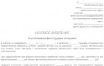
ACT No. _____ from __________ visual and/or measuring quality control of welds during the joint welding process
__________________________________________________________________________ (product name and connection number)
1. This act certifies the fact that the welder performed _________________________________________________________________________ full name, brand
Connections _________ (see welding form), type(s) of connections
Completed __________________________________________________________ indicate the welding method and position
In accordance with the requirements of welding technology ______________________ _______________________________________________________________________ indicate the technology code
And inaccessible for control __________________________________________ indicate the method of control prescribed
Design documentation
2. With layer-by-layer visual and measurement control with quality assessment according to the standards of _____________________________________ for category ________________________________________________________________________________ (code or name of ND)
It has been established that the welded joint is recognized as suitable and meets the requirements of __________________________________________________________ (indicate RD or design documentation)
Control completed by: ___________________________________________________ Qualification level, Last name, initials, signature No. qualification certificate
Head of visual and measurement control: ____________________________________________________________ Last name, initials, signature
Note. A report is drawn up for each welded structure (joint or group of joints) subjected to control during the welding process.
Requirements for the preparation of the "Protocol of sizes _____________" (product)
A size protocol is drawn up only when this is indicated in the ND or design specification documentation for the controlled product.
The product size protocol (table) must contain the actual dimensions of the product, made in certain sections, which are specified by the “Measurement Scheme ____________”. The size protocol form is determined (product)
During design and technological preparation of control work. The protocol is signed by the persons who performed the measurements and by the head of the visual and measurement control work, indicating the surname and initials.
Requirements for the content of the "Work Log"
and recording the results of visual
The results of control of products, products and objects are recorded in the “Journal of work and registration of results of visual and measurement control”, in which they indicate:
1) name and type (type) of the controlled object, its number or code;
2) location and, if necessary, sizes of controlled areas at the control object;
3) conditions for carrying out control;
4) production control document, its number;
5) method of measurement control and used devices (tools);
and measuring control"
7) the main characteristics of defects identified during inspection (shape, size, location or orientation relative to the basic axes or inspection surfaces);
8) name or code of the RD according to which the quality assessment was performed;
9) assessment of control results;
10) date of control.
Note. It is allowed to use instead of the above other forms of documents developed by the organization in accordance with the requirements of the current regulatory and technical documentation, which provide identification and traceability of parts, assemblies, products during the manufacturing process (installation, repair), recording of controlled parameters, volumes and control methods, preparation of reporting and accounting documentation for visual and measurement control.