Straight pipe threads are mainly used for pipe connections, pipeline fittings and fittings. This thread covers diameters from 1/16 to 6" with the number of threads per 1" from 28 to 11.
The nominal diameter of a pipe thread is conventionally related to the internal diameter of the pipe. In terms of the ratio of pitches and diameters, pipe thread is a crushed inch thread according to OST 1260. Therefore, pipe thread at one time, before the standardization of small metric threads, was used not only for pipe connections, but also for fasteners, when there was a need to make threads with relatively in small steps, with large diameters. Pipe thread is a pan-European standard for pipes and pipe connections.
STRAIGHT PIPE THREAD DIMENSIONS
(GOST 6357-81)
The standard applies to cylindrical pipe threads used in cylindrical threaded connections, as well as in connections of internal cylindrical threads with external conical threads in accordance with GOST 6211-81.
Tolerances (according to GOST 6357-81) of the average thread diameter are established in two accuracy classes - A and B. Tolerances of the average thread diameter are total. Tolerances for diameters d 1 and D are not established.

dimensions, mm
| Thread designation | Number of steps z at a length of 25.4 mm | Step P | Thread diameter | Working height of profile H 1 | Curvature radius R | H | H/6 | |||
| 1st row | 2nd row | outer d = D | average d 2 = D 2 | internal d 1 = D 1 | ||||||
| 1/16" 1/8" | - | 28 | 0,907 | 7,723 | 7,142 | 6,561 | 0,580777 | 0,124557 | 0,871165 | 0,145194 |
| 9,728 | 9,147 | 8,566 | ||||||||
| 1/4" 3/8" | - | 19 | 1,337 | 13,157 | 12,301 | 11,445 | 0,856117 | 0,183603 | 1,284176 | 0,214029 |
| 16,662 | 15,806 | 14,950 | ||||||||
| 1/2" | 5/8" | 14 | 1,814 | 20,955 | 19,793 | 18,631 | 1,161553 | 0,249115 | 1,742331 | 0,290389 |
| 22,911 | 21,749 | 20,587 | ||||||||
| 26,441 | 25,279 | 24,117 | ||||||||
| 30,201 | 29,039 | 27,877 | ||||||||
| 1" | 1 1/8" 1 3/4" | 11 | 2,309 | 33,249 | 31,770 | 30,291 | 1,478515 | 0,317093 | 2,217774 | 0,369629 |
| 37,897 | 36,418 | 34,939 | ||||||||
| 41,910 | 40,431 | 38,952 | ||||||||
| 44,323 | 42,844 | 41,365 | ||||||||
| 47,803 | 46,324 | 44,845 | ||||||||
| 53,746 | 52,267 | 50,788 | ||||||||
| 59,614 | 58,135 | 56,656 | ||||||||
| 2 1/2" 3 1/2" | 2 1/4" 3 3/4" |
65,710 | 64,231 | 62,752 | ||||||
| 75,184 | 73,705 | 72,226 | ||||||||
| 81,534 | 80,055 | 78,576 | ||||||||
| 87,884 | 86,405 | 84,926 | ||||||||
| 93,980 | 92,501 | 91,022 | ||||||||
| 100,330 | 98,851 | 97.372 | ||||||||
| 106,680 | 105,201 | 103,722 | ||||||||
| 4" | 4 1/2" 5 1/2" |
113,030 | 111,551 | 110.072 | ||||||
| 125,730 | 124,251 | 122,772 | ||||||||
| 138,430 | 136,951 | 135,472 | ||||||||
| 151,130 | 149,651 | 148,172 | ||||||||
| 163,830 | 162,351 | 160,872 | ||||||||
| When choosing thread sizes, row 1 should be preferred to row 2. | ||||||||||
MAKE-UP LENGTHS according to GOST 6357-81
Make-up lengths are divided into two groups: normal N and long L.
dimensions, mm
| Designation thread size | Step P | Make-up length | |
| N | L | ||
| 1/16", 1/8" | 0,907 | St. 4 to 12 | St. 12 |
| 1/4", 3/8" | 1,337 | St. 5 to 16 | St. 16 |
| 1/2", 5/8" | 1,814 | St. 7 to 22 | St. 22 |
| 1", 1 1/8", 1 1/4", 1 3/8" | 2,309 | St. 10 to 30 | St. 30 |
| 1 1/2", 1 3/4", 2", 2 1/4", 2 1/2", 2 3/4", 3" | St. 12 to 36 | St. 36 | |
| 3 1/4", 3 1/2", 3 3/4", 4", 4 1/2", 5", 5 1/2", 6" | St. 13 to 40 | St. 40 | |
| Numerical values of make-up lengths are established empirically. | |||
The symbol for left-hand threads is supplemented with the letters LH.
Examples of symbols for threads of accuracy class A:
G 1 1/2-A
left-hand thread accuracy class B:
G 1 1/2 LH-B
The make-up length N is not indicated in the thread designation.
The make-up length L is indicated in millimeters.
G 1 1/2 LH-B-40
The fit is indicated by a fraction: the numerator of which indicates the designation of the accuracy class of the internal thread, and the denominator indicates the designation of the accuracy class of the external thread.
G 1 1/2-A/A; G 1 1/2 LH-A/B
The connection of an internal pipe cylindrical thread of accuracy class A according to this standard with an external pipe conical thread in accordance with GOST 6211-81 is designated as follows:
G/R 1 1/2 - A
P.S. At one time, the profile of cylindrical pipe threads (according to OST 266) extended to diameters up to 18" with the number of threads per 1" from 28 to 8.
Related documents:
- holes for threading
GOST 3469-91 - Microscopes. Lens thread. Dimensions
GOST 4608-81 - Metric thread. Preference fits
GOST 5359-77 - Eyepiece thread for optical instruments. Profile and dimensions
GOST 6042-83 - Edison round thread. Profiles, dimensions and limits
GOST 6111-52 - Conical inch thread with a profile angle of 60 degrees
GOST 6211-81 - Tapered pipe thread
GOST 6357-81 - Cylindrical pipe thread
GOST 8762-75 - Round thread with a diameter of 40 mm for gas masks and calibers for it. Main Dimensions
GOST 9000-81 - Metric threads for diameters less than 1 mm. Tolerances
GOST 9484-81 - Trapezoidal thread. Profiles
GOST 9562-81 - Single-start trapezoidal thread. Tolerances
GOST 9909-81 - Tapered thread of valves and gas cylinders
GOST 10177-82 - Persistent thread. Profile and main dimensions
GOST 11708-82 - Thread. Terms and definitions
GOST 11709-81 - Metric thread for plastic parts
GOST 13535-87 - Reinforced thrust thread 45 degrees
GOST 13536-68 - Round thread for sanitary fittings. Profile, main dimensions, tolerances
GOST 16093-2004 - Metric thread. Tolerances. Landings with clearance
GOST 16967-81 - Metric threads for instrument making. Diameters and pitches
GOST 24737-81: Single-start trapezoidal thread. Main Dimensions
GOST 24739-81 - Multi-start trapezoidal thread
GOST 25096-82 - Persistent thread. Tolerances
GOST 25229-82 - Metric tapered thread
GOST 28487-90: Conical locking threads for drill string elements. Profile. Dimensions. Tolerances
It would seem that there is something complicated in the pipes? Connect and twist... But, if you are not a plumber or an engineer with a specialized education, then you will definitely have questions for answers to which you will have to go wherever you look. And most likely the first thing they look at is the Internet)
We have previously talked about the diameters of metal pipes in this material. Today we will try to clarify the threaded connections of pipes for various purposes. We tried not to clutter the article with definitions. Basic terminology contains GOST 11708-82 which everyone can familiarize themselves with.
Pipe cylindrical thread. GOST 6357 - 81

Direction: Left
Accuracy class: Class A (increased), Class B (normal)
Why in inches?
The inch size came to us from Western colleagues, since the requirements of the current in the post-Soviet space GOST and are formulated on the basis of thread B.S.W.(British Standard Whitworth or Whitworth carving). Joseph Whitworth (1803 - 1887), a design engineer and inventor, demonstrated the screw profile of the same name for detachable connections back in 1841 and positioned it as a universal, reliable and convenient standard.
This type of thread is used both in the pipes themselves and in the elements of pipe connections: locknuts, couplings, elbows, tees ( see picture above). In the profile section we see an isosceles triangle with an angle of 55 degrees and roundings at the tops and bottoms of the contour, which are made for high tightness of the connection.
Threading of threaded connections is carried out on sizes up to 6”. All larger pipes are fixed by welding to ensure a reliable connection and prevent rupture.
Symbol in the international standard
International: G
Japan: PF
UK: BSPP
The letter G and the bore diameter (internal Ø) of the pipe are indicated in inches. The outer diameter of the thread itself is not included in the designation.
Example:
G 1/2- cylindrical external pipe thread, internal pipe Ø 1/2"". The outer diameter of the pipe will be 20.995 mm, the number of steps over a length of 25.4 mm will be 14.
The accuracy class (A, B) and the direction of turns (LH) can also be indicated.
For example:
G 1 ½ - B- cylindrical pipe thread, internal Ø 1 ½ inches, accuracy class B.
G1 ½ LH- B- cylindrical pipe thread, internal Ø 1 ½ inches, accuracy class B, left.
The make-up length is indicated by the last one in mm: G 1 ½ -B-40.
For internal pipe cylindrical threads, only the Ø of the pipe for which the hole is intended will be indicated.
Parallel Pipe Thread Size Chart
| Thread size |
Thread pitch, mm |
Threads per inch |
Thread diameters |
|||
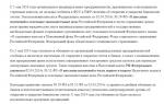
How to determine the pitch of an inch thread

I’ll give you a picture from the English-language Internet that clearly demonstrates the technique. Pipe threads are characterized not by the size between the tops of the profile, but by the number of turns per 1 inch along the axis of the thread. A regular tape measure or ruler can help. Apply it, measure one inch (25.4 mm) and visually count the number of steps.
In the picture with an example ( see above) threads - from English these are literally “threads of thread”. In this case there are 18 of them. by one inch.
It’s even easier if you have a thread gauge for inch threads lying around in your tool box. It is very convenient to take measurements, but it must be remembered that inch threads may differ in the apex angle of 55° and 60°.
Tapered pipe threads


drawing of pipe tapered threads
Tapered pipe thread GOST 6211-81 (1st standard size)
Parameter Unit: Inch
Corresponds to the rounded profile of a cylindrical pipe thread with an angle of 55°. Cm. top part (I) of the three-dimensional image "drawing of pipe tapered threads".
Symbol
International: R
Japan: PT
UK: BSPT
The letter R and the nominal diameter Dy are indicated. The designation R means external thread, Rc internal, Rp internal cylindrical. By analogy with cylindrical pipe threads, LH is used for left-hand threads.
Examples:
R1 ½- external pipe thread, nominal diameter Dy = 1 ½ inches.
R1 ½ LH- external pipe thread, nominal diameter Dy = 1 ½ inches, left.
Conical inch thread GOST 6111 - 52 (2nd standard size)
Parameter Unit: Inch
Has a profile angle of 60°. Cm. lower part (II) of the three-dimensional image "drawing of pipe tapered threads". It is used in pipelines (fuel, water, air) of machines and machines with relatively low pressure. The use of this type of connection assumes tightness and locking of the thread without additional special means (linen threads, yarn with red lead).
Symbol
Example:K ½ GOST 6111 - 52
It stands for: inch conical thread with an outer and inner diameter in the main plane approximately equal to the outer and inner Ø of a cylindrical pipe thread G ½
Table of main parameters of tapered inch threads
| Thread size designation (d, inches) | Number of threads per 1" n | Thread pitch S, mm | Thread length, mm | Outer thread diameter in the main plane d, mm | |
| Working l1 | From the end of the pipe to the main plane l2 | ||||
| 1/16 | 27 | 0,941 | 6,5 | 4,064 | 7,895 |
| 1/8 | 27 | 0,941 | 7,0 | 4,572 | 10,272 |
| 1/4 | 18 | 1,411 | 9,5 | 5,080 | 13,572 |
| 3/8 | 18 | 1,411 | 10,5 | 6,096 | 17,055 |
| 1/2 | 14 | 1,814 | 13,5 | 8,128 | 21 793 |
| 3/4 | 14 | 1,814 | 14,0 | 8,611 | 26,568 |
| 1 | 11 1/2 | 2,209 | 17,5 | 10,160 | 33,228 |
| 1 1/4 | 11 1/2 | 2,209 | 18,0 | 10,668 | 41,985 |
| 1 1/2 | 11 1/2 | 2,209 | 18,5 | 10,668 | 48,054 |
| 2 | 11 1/2 | 2,209 | 19,0 | 11,074 | 60,092 |
Metric tapered thread. GOST 25229 - 82

Parameter unit: mm
Produced on surfaces with a taper of 1:16
Used when connecting pipelines. The angle at the top of the turn is 60°. The main plane is shifted relative to the end ( see pic above).
Symbol
The letters MK are followed by an indication of the diameter in the main plane and the thread pitch in mm: MK 30x2
Metric Tapered Thread Size Chart
| Thread diameter d for row | Step P | Thread diameter in the main plane | ||||||
| 1 | 2 | d = D | d2=D2 | d1=D1 | l | l1 | l2 | |
| 6 | --- | 1 | 6,000 | 5,350 | 4,917 | 8 | 2,5 | 3 |
| 8 | --- | 8,000 | 7,350 | 6,917 | ||||
| 10 | --- | 10,000 | 9,350 | 8,917 | ||||
| 12 | --- | 1,5 | 12,000 | 11,026 | 10,376 | 11 | 3,5 | 4 |
| --- | 14 | 14,000 | 13,026 | 12,376 | ||||
| 16 | --- | 16,000 | 15,026 | 14,376 | ||||
| --- | 18 | 18,000 | 17,026 | 16,376 | ||||
| 20 | --- | 20,000 | 19,026 | 18,376 | ||||
| --- | 22 | 22,000 | 21,026 | 20,376 | ||||
| 24 | --- | 24,000 | 23,026 | 22,376 | ||||
| --- | 27 | 2 | 27,000 | 25,701 | 24,835 | 16 | 5 | 6 |
| 30 | --- | 30,000 | 28,701 | 27,835 | ||||
| --- | 33 | 33,000 | 31,701 | 30,835 | ||||
| 36 | --- | 36,000 | 34,701 | 33,835 | ||||
Characteristics of cylindrical pipe/inch threads relative to metric
The main characteristics of "inch" and "pipe" cylindrical threads in relation to "metric" threads for basic sizes.
|
Nominal thread diameter in dm |
Inch thread |
Pipe thread |
||||
|
outer diameter, mm |
number of threads per 1" |
outer diameter, mm |
number of threads per 1" |
|||
BSP British standard pipe thread- cylindrical pipe thread, also referred to as BSPP.
BSP threads are interchangeable with threads of the domestic standard GOST 6357-81.
It is used in cylindrical threaded connections, as well as in connections of internal cylindrical threads with external conical threads BSPT (GOST 6211-81).
Basic standards:
GOST 6357-81 - Basic standards of interchangeability. Cylindrical pipe thread.
ISO R228
EN 10226
JIS B 0202
Thread parameters: inch thread with a profile angle at the apex of 55°, theoretical profile height Н=0.960491Р.
Symbol according to GOST 6357-81: letter G, the numerical value of the nominal thread diameter in inches (inch), the accuracy class of the average diameter (A, B), and the letters LH for left-hand threads.
For example, a thread with a nominal diameter of 1.1/8", accuracy class A is designated as: G 1.1/8"-A.
The pitch of a cylindrical pipe thread according to GOST 6357-81 has four values indicated in Table 2.
The main thread dimensions of GOST 6357-81 (BSP) are given in Table 2.
Commentary on Table 2.
d is the outer diameter of the external thread (pipe);
D—outer diameter of the internal thread (coupling);
D 1 - internal diameter of the internal thread;
d 1 - internal diameter of the external thread;
D 2 - average diameter of internal thread;
d 2 - average diameter of the external thread.
When selecting the pipe thread size first row should be preferred second.
Table 2 |
|||||||||||||||||||||||||||||||||||||||||||||||||||||||||||||||||||||||||||||||||||||||||||||||||||||||||||||||||||||||||||||||||||||||||||||||||||||||||||
Designation of the size of a cylindrical pipe thread (G), steps and nominal values of the outer, middle and inner diameters of the thread (according to GOST 6357-81), mm |
|||||||||||||||||||||||||||||||||||||||||||||||||||||||||||||||||||||||||||||||||||||||||||||||||||||||||||||||||||||||||||||||||||||||||||||||||||||||||||
|
|||||||||||||||||||||||||||||||||||||||||||||||||||||||||||||||||||||||||||||||||||||||||||||||||||||||||||||||||||||||||||||||||||||||||||||||||||||||||||
* Whitworth cut
BSPT British standard pipe tapered thread - conical pipe thread.
Based on BSW (British Standard Whitworth) threads, known as Whitworth pipe threads*.
BSPT threads are interchangeable with threads of the domestic standard GOST 6211-81.
It is used in conical threaded connections, as well as in connections of external conical threads with internal cylindrical threads in accordance with GOST 6357-81.
Basic standards for BSPT threads:
GOST 6211-81 - Basic standards of interchangeability. Conical pipe thread.
ISO R7
DIN 2999
BS 21
JIS B 0203
Thread parameters: inch thread with a taper of 1:16 (taper angle 3°34'48"). Profile angle at the apex 55°.
Symbol according to GOST 6211-81: letter R for external thread and Rc for internal thread, numerical value of the nominal thread diameter in inches (inch), letters LH for left-hand thread. For example, a thread with a nominal diameter of 1.1/4" is designated as: R 1.1/4".
Table 1 |
||||||||||||||||||||||||||||||||||||||||||||||||||||||||||||||||||||||||||||||||||||||||||||||||||||||||||||||||
Designation of thread size, steps and nominal values of the outer, middle and inner diameters of conical pipe threads (R), mm |
||||||||||||||||||||||||||||||||||||||||||||||||||||||||||||||||||||||||||||||||||||||||||||||||||||||||||||||||
|
||||||||||||||||||||||||||||||||||||||||||||||||||||||||||||||||||||||||||||||||||||||||||||||||||||||||||||||||
*Whitworth - (Whitworth) Joseph (lived 1803-87), English engineer and industrialist. Proposed the screw thread profile in 1841 Whitworth cut. In 1851 he created a high-precision measuring machine and developed a system for standardizing threads and gauges.
NPTF National Pipe Tapered Fuel - national pipe tapered fuel thread.
NPTF - sealed thread. Compaction occurs due to compression of the threads.
Tapered fuel pipe threads are specified by ANSI/ASME B1.20.3
The NPTF fitting has a conical thread with a taper of 1:16 (cone angle φ=3°34’48").
The NPTF fitting is compatible with NPTF, NPSF or NPSM female threads.
NPTF threads are used in hydraulic systems, although the National Hydraulic Power Association (NFPA) does not recommend them for use in hydraulics.
On fittings with NPTF threads, to distinguish them from BSPT threads, a mark is usually placed on the edges of the hexagon
Nominal size | Outer diameter, mm | Threaded hole, mm | TPI, threads per inch | Coil pitch, mm |
NPTF thread 1/16" | ||||
NPTF 1/8" thread | ||||
NPTF 1/4" thread | ||||
NPTF 3/8" thread | ||||
NPTF 1/2" thread | ||||
NPTF 3/4" thread | ||||
NPTF 1" thread | ||||
NPTF 1.1/4" thread | ||||
NPTF 1.1/2" thread | ||||
NPTF thread 2" | ||||
NPTF 2.1/2" thread | ||||
NPTF 4" thread |
Taper thread (NPT) with a taper of 1:16 (cone angle φ=3°34'48") or cylindrical (NPS) thread. Profile angle at the apex 60°, theoretical profile height Н=0.866025Р.
Tapered NPT threads are specified by ANSI/ASME B1.20.1.
NPT thread corresponds to GOST 6111-52 - Conical inch thread with a profile angle of 60 degrees.
Nominal size | Outer diameter, mm | Threaded hole, mm | TPI, threads per inch | Coil pitch, mm |
1/16" NPT thread | ||||
1/8" NPT thread | ||||
1/4" NPT thread | ||||
NPT 3/8" thread | ||||
1/2" NPT thread | ||||
NPT 3/4" thread | ||||
1" NPT thread | ||||
NPT 1.1/4" thread | ||||
NPT 1.1/2" thread | ||||
NPT 2" thread | ||||
NPT thread 2.1/2" NPT | ||||
NPT 3" thread | ||||
NPT 3.1/2" thread | ||||
NPT 4" thread | ||||
NPT 5" thread | ||||
NPT 6" thread | ||||
NPT 8" thread | ||||
NPT 10" thread | ||||
12" NPT thread |
Metric threads- is widely used both in Russia and in world practice. Metric connections are widely used pipe connections ISO 8434-1 DIN 2353.
Hydraulic connections mainly use two pitches of metric threads: pitch 1.5 and pitch 2.0.
Dimensions of commonly used hydraulic threads with a pitch of 1.5 mm: M12x1.5; M14x1.5; M16x1.5; M18x1.5; M20x1.5; M22x1.2; M24x1.5; M26x1.5; M27x1.5; M30x1.5; M33x1.5; M36x1.5; M38x1.5 M45x1.5 M52x1.5.
Dimensions of commonly used hydraulic threads with a pitch of 2.0 mm: M30x2.0; M33x2.0; M36x2.0; M42x2.0; M45x2.0; M52x2.0.
Dimensions of metric threads in fittings for high pressure hoses domestic production(the so-called DK standard): DK(G)M16x1.5; DK(G)M18x1.5; DK(G)M20x1.5; DK(G)M22x1.5; DK(G)M27x1.5; DK(G)M33x1.5; DK(G)M33x2.0; DK(G)M36x1.5; DK(G)M36x2.0; DK(G)M42x2.0.
All profile parameters are measured in fractions of a meter (millimeters). Nominal diameter from 1 to 600 mm. Thread pitch from 0.0075 to 6 mm. Equilateral triangle profile (vertex angle 60°) with theoretical profile height H=0.866025404Р.
Basic standards for metric threads:
GOST 9150-2002 (ISO 68-1-98): Basic standards of interchangeability. Metric thread. Profile. Replaces GOST 9150-81 from January 1, 2004.
GOST 8724-2002 Basic standards of interchangeability. Metric thread. Diameters and steps.
GOST 9000-81 Basic standards of interchangeability. Metric thread for diameters less than 1 mm. Tolerances.
GOST 11708-82 Basic standards of interchangeability. Thread. Terms and definitions.
GOST 16093-81 Basic standards of interchangeability. Metric thread. Tolerances. Landings with clearance.
GOST 24705-81 Basic standards of interchangeability. Metric thread. Basic dimensions.
Standards: GOST 9150-81 - Basic norms of interchangeability. Metric thread. Profile.
GOST 8724-81 - Basic standards of interchangeability. Metric thread. Diameters and steps.
ISO 965-1:1998 - ISO metric threads for general purposes. Tolerances. Part 1. Principles and main characteristics.
ISO 965-2:1998 - ISO metric threads for general purposes. Tolerances. Part 2. Limit dimensions of threads for general purpose bolts and nuts. Middle class accuracy.
ISO 965-3:1998 - ISO metric threads for general purposes. Tolerances. Part 3. Deviations for structural threads.
ISO 965-4:1998 - ISO metric threads for general purposes. Tolerances. Part 4: Limit dimensions for hot-dip galvanized external screw threads for assembly with internal screw threads tapped to tolerance position H or G after galvanization.
ISO 965-5:1998 - ISO metric threads for general purposes. Tolerances. Part 5: Dimensions for internal screw threads of screws for assembly with external hot-dip galvanized screw threads, with maximum size tolerance positions h before galvanization.
ISO 68-1 - General purpose ISO screw threads. Main profile. Metric thread.
ISO 261:1998 - ISO metric threads for general purposes. General view.
ISO 262:1998 - ISO metric threads for general purposes. Selected sizes for screws, bolts and nuts.
BS 3643 - ISO metric screw threads.
DIN 13-12-1988 - Basic and precision ISO metric threads with diameters from 1 to 300 mm. Choice of diameters and pitches.
ANSI B1.13M, ANSI B1.18M - Metric thread M with profile based on ISO standard 68.
Symbol: the letter M (metric), the numerical value of the nominal thread diameter in millimeters, the numerical value of the pitch (for fine-pitch threads) and the letters LH for left-hand threads. For example, a thread with a nominal diameter of 16 mm with a coarse pitch is designated as M16; thread with a nominal diameter of 36 with a fine pitch of 1.5 mm - M36x1.5; the same diameter and pitch but left-hand thread M36x1.5LH.
Notes:
1. The shape of the bolt thread root is not regulated and can be either rounded or flat-cut. A rounded cavity shape is preferred.
2. The shape of the nut thread root is not regulated.
d - outer diameter of the external thread (bolt); D - outer diameter of the internal thread (nut); d2 - average bolt diameter; D2 - average diameter of the nut; d1 - internal diameter of the bolt; D1 - internal diameter of the nut; P - thread pitch; H is the height of the original triangle; R is the nominal radius of curvature of the bolt cavity; H1 - working height of the profile
Step R | ||||||
UNF/UTS (Unified Thread Standard - inch cylindrical thread widespread in the USA and Canada.
Thread profile UN/UNF: angle at apex 60°, theoretical profile height H=0.866025P.
The apex angle and profile height fully comply with metric threads, however, all dimensions are based on the inch measurement system and are indicated in fractions of an inch.
Depending on the step, it is divided into : UNC (Unified Coarse), UNF (Unified Fine), UNEF (Unified Extra Fine), UNS (Unified Special).
Mainly used in hydraulic connections UNF thread fittings.
Nominal thread size UNF | Outer Diameter, Inch | Outer diameter, mm | Diameter of the hole for the tap (inner diameter of the nut), mm | TPI threads per inch | Coil pitch, mm |
UNF thread 0-80 | |||||
Thread UNF 1-72 | |||||
UNF 2-64 thread | |||||
UNF 3-56 thread | |||||
UNF 4-48 thread | |||||
UNF 5-44 thread | |||||
UNF 6-40 thread | |||||
UNF 8-36 thread | |||||
Thread UNF 10-32 | |||||
Thread UNF 12-28 | |||||
UNF thread 1/4"-28 | |||||
UNF thread 5/16"-24 | |||||
UNF thread 3/8"-24 | |||||
UNF thread 7/16"-20 | |||||
UNF thread 1/2"-20 | |||||
UNF thread 9/16"-18 | |||||
UNF thread 5/8"-18 | |||||
UNF thread 3/4"-16 | |||||
UNF thread 7/8"-14 | |||||
UNF thread 1"-12 | |||||
UNF thread 1.1/8"-12 | |||||
UNF thread 1.1/4"-12 | |||||
UNF thread 1.3/8"-12 | |||||
UNF thread 1.1/2"-12 |
GOST 6211-81
Group G13
INTERSTATE STANDARD
Basic norms of interchangeability
CONICAL PIPE THREAD
Basic norms of interchangeability. Pipe taper thread
Date of introduction 1983-01-01
1. DEVELOPED AND INTRODUCED by the Ministry of Machine Tool and Tool Industry
2. APPROVED AND ENTERED INTO EFFECT by the Resolution State Committee USSR according to standards dated December 30, 1981 N 5789
3. INSTEAD GOST 6211-69
4. The standard fully complies with ST SEV 1159-78
5. REFERENCE REGULATIVE AND TECHNICAL DOCUMENTS
Item number |
|
Introductory part, 1.2, 3.3, 4.2 |
6. REISSUE
This standard applies to conical pipe threads with a taper of 1:16, used in conical threaded connections, as well as in connections of external conical threads with internal cylindrical threads with a profile in accordance with GOST 6357 and establishes the profile, main dimensions and tolerances of conical threads, as well as tolerances of internal cylindrical pipe thread connected to an external conical thread.
1. PROFILE
1. PROFILE
1.1. The nominal profile of the pipe conical thread (external and internal) and the dimensions of its elements must correspond to those indicated in Figure 1 and Table 1.
Damn.1. Nominal profile of pipe tapered thread (external and internal) and dimensions of its elements
Taper ; ; ; - outer diameter of the external tapered thread; - internal diameter of external tapered thread; - average diameter of external tapered thread; - outer diameter of the internal tapered thread; - internal diameter of the internal tapered thread; - average diameter of the internal tapered thread; - thread pitch; - cone angle; - slope angle; - height of the original triangle; - working height of the profile; - radius of curvature of the top and bottom of the thread; - cutting off the tops and bottoms of the thread.
Table 1
Dimensions in millimeters
Number of steps per length 25.4 mm | |||||
Note. The numerical values of the steps are determined from the ratio with rounding to the third decimal place and taken as the initial ones when calculating the main elements of the profile.
1.2. The dimensions of the internal cylindrical thread profile elements are in accordance with GOST 6357.
2. MAIN DIMENSIONS
2.1. The designation of thread size, steps and nominal values of the main dimensions of conical (external and internal) threads must correspond to those indicated in Figure 2 and Table 2.
Damn.2. Designation of thread size, steps and nominal values of the main sizes of tapered (external and internal) threads
Working thread length; - length of external thread from end to main plane
Table 2
Dimensions in millimeters
Designation | Thread diameters in the main plane | Thread length |
||||
Shorter thread lengths may be used.
2.2. Numerical values of diameters and are calculated using the following formulas
The numerical values of the diameter are established empirically.
2.3. The difference between the actual dimensions must be no less than the difference between the nominal dimensions and indicated in Table 2.
2.4. The length of the internal tapered thread must be at least 0.8 (where - in accordance with Table 3)*.
________________
* The text of the document corresponds to the original. - Database manufacturer's note.
Table 3
Dimensions in millimeters
Thread size designation | Offset of the main thread plane | Maximum deviations of the diameter of internal cylindrical threads |
|
2; 3; 3; 4; 5; 6 | |||
Note. Maximum deviations do not apply to threads with lengths shorter than those indicated in Table 2.
2.5. The designation of thread sizes, pitches and nominal values of the outer, middle and inner diameters of the internal cylindrical thread must correspond to those indicated in Figure 3 and Table 2.
Damn.3. Designation of thread sizes, pitches and nominal values of outer, middle and inner diameters of internal cylindrical threads
2.6. The design of parts with internal threads (conical and cylindrical) must ensure screwing in of external conical threads to a depth of at least .
3. TOLERANCES
3.1. The axial displacement of the main plane of the external and internal threads (Fig. 4) relative to the nominal location should not exceed the values specified in Table 3.
Damn.4. Axial displacement of the main plane of external and internal threads
Note. In the main plane, the average diameter has a nominal value.
The displacement of the main plane is total, including deviations of the average diameter, pitch, angle of inclination of the side of the profile and cone angle.
3.2. The maximum deviations of the average diameter of the internal cylindrical thread must correspond to those indicated in Table 3.
3.3. It is allowed to connect an external conical thread with an internal cylindrical thread of accuracy class A according to GOST 6357.
4. NOTATION
4.1. The thread designation must include: letters ( - for conical external threads, - for conical internal threads, - for cylindrical internal threads) and a designation of the thread size.
The symbol for left-hand threads is supplemented with the letters .
Examples of thread symbols:
- external pipe conical thread 1:
Internal pipe tapered thread 1:
Internal pipe straight thread 1:
Left hand thread:
4.2. A threaded connection is designated by a fraction, for example, or, the numerator of which indicates the letter designation of the internal thread, and the denominator - the external thread, and the thread size.
Examples of symbols for threaded connections:
- pipe conical thread (internal and external):
Internal pipe cylindrical thread (with tolerances according to this standard) and external pipe tapered thread:
Internal pipe cylindrical thread of accuracy class A according to GOST 6357 and external pipe conical thread:
APPENDIX (reference). LIMIT DEVIATIONS OF INDIVIDUAL THREAD PARAMETERS
APPLICATION
Information
1. This appendix contains information on the maximum deviations of individual thread parameters, which are the initial ones when designing a thread-forming tool and calculating thread gauges and are not subject to mandatory control, unless specifically stated.
2. The maximum deviations of the cut of the peaks and valleys (size), the angle of inclination of the side of the profile, the pitch and the cone angle (the difference in the average diameters along the length) of the conical thread are shown in Figure 1 and in the table.
Damn.1. Limit deviations of the cut of the peaks and valleys, the angle of inclination of the side of the profile, the pitch and the angle of the cone
es - upper deviation of the cut of the top and bottom of the external thread; ES - upper deviation of the cut of the top and bottom of the internal thread; ei - lower deviation of the cut of the top and bottom of the external thread; EI - lower deviation of the cut of the top and bottom of the internal thread; - tolerance of the angle of inclination of the side of the thread profile.
3. The maximum deviations of the cut of the peaks and valleys (size) of the internal cylindrical thread (Fig. 2) should not exceed:
- cut of vertices +0.05 mm (ES=+0.05 mm, EI=0);
- cut of depressions ±0.025 mm (ES=+0.025 mm, EI=-0.025 mm)
Damn.2. Limit deviations of cut of tops and bottoms of internal cylindrical threads
Dimensions in millimeters
Thread size designation | Prev. off | Average diameter difference |
||||||||
step on length | ||||||||||
peaks | depressions | Prev. off |
||||||||
external thread | internal thread |
|||||||||
0,028 | 0,014 |
|||||||||
0,042 | 0,021 |
|||||||||
0,044 | 0,022 |
|||||||||
0,058 | 0,028 |
|||||||||
0,066 | 0,034 |
|||||||||
0,073 | 0,036 |
|||||||||
0,089 | 0,045 |
|||||||||
0,111 | 0,056 |
|||||||||
0,122 | 0,062 |
|||||||||
0,073 |
||||||||||
0,155 | 0,078 |
|||||||||
0,177 | 0,089 |
|||||||||
0,200 | 0,101 |
|||||||||
Note. The value refers to the distances between threads. The actual deviation may have a minus or plus sign.
Electronic document text
prepared by Kodeks JSC and verified against:
official publication
Inch and special threads: Sat. GOST. -
M.: IPK Standards Publishing House, 2003
MAIN DIMENSIONS
PIPE TAPER THREAD
(GOST 6211-81)
The standard applies to tapered pipe threads with a taper 1: 16 . used in conical threaded connections, as well as in connections of external conical threads with internal cylindrical threads with a profile in accordance with GOST 6357-81.
Taper 2tg(φ /2) = 1: 16;
φ = 3°34"48"; φ/2 = 1°47"24";
d and D are the outer diameters of the external and internal threads, respectively;
d 1 and D 1 - internal diameters of external and internal threads, respectively;
d 2 and D 2 - average diameters of external and internal threads, respectively;
P - thread pitch;
φ - cone angle; φ/2 - slope angle;
H - height of the original triangle;
H 1 - working height of the profile;
R - radius of curvature of the top and bottom of the thread;
C - cut of the tops and bottoms of the thread;
l 1- working thread length;
l 2- the length of the external thread from the end to the main plane.
dimensions, mm
| Thread size designation | Step P | Number of steps per length 25.4 mm | H | H 1 | C | R | Thread diameters in the main plane | Thread length | |||
| d = D | d2 = D2 | d 1 = D 1 | l 1 | l 2 | |||||||
| 1/16" | 0,907 | 28 | 0,870935 | 0,580777 | 0,145079 | 0,124511 | 7,723 | 7,142 | 6,561 | 6,5 | 4,0 |
| 1/8" | 9,728 | 9,147 | 8,566 | ||||||||
| 1/4" | 1,337 | 19 | 1,283837 | 0,856117 | 0,213860 | 0,183541 | 13,157 | 12,301 | 11,445 | 9,7 | 6,0 |
| 3/8" | 16,662 | 15,806 | 14,950 | 10,1 | 6,4 | ||||||
| 1/2" | 1,814 | 14 | 1,741870 | 1,161553 | 0,290158 | 0,249022 | 20,955 | 19,793 | 18,631 | 13,2 | 8,2 |
| 3/4" | 26,441 | 25,279 | 24,117 | 14,5 | 9,5 | ||||||
| 1" | 2,309 | 11 | 2,217187 | 1,478515 | 0,369336 | 0,316975 | 33,249 | 31,770 | 30,291 | 16,8 | 10,4 |
| 1 1/4" | 41,910 | 40,431 | 38,952 | 19,1 | 12,7 | ||||||
| 1 1/2" | 47,803 | 46,324 | 44,845 | ||||||||
| 2" | 59,614 | 58,135 | 56,656 | 23,4 | 15,9 | ||||||
| 2 1/2" | 75,184 | 73,705 | 72,226 | 26,7 | 17,5 | ||||||
| 3" | 87,884 | 86,405 | 84,926 | 29,8 | 20,6 | ||||||
| 3 1/2" | 100,330 | 98,851 | 97,372 | 31,4 | 22,2 | ||||||
| 4" | 113,030 | 111,551 | 110,072 | 35,8 | 25,4 | ||||||
| 5" | 138,430 | 136,951 | 135,472 | 40,1 | 28,6 | ||||||
| 6" | 163,830 | 162,351 | 160,872 | ||||||||
DESIGNATION
The thread designation must include: letters (R - for conical external threads, R c - for conical internal threads, R p - for cylindrical internal threads) and a designation of the thread size:
external pipe tapered thread - R 1 1/2
internal pipe conical thread - R with 1 1/2
internal pipe cylindrical thread - R p 1 1/2
left thread - R 1 1/2LH, R with 1 1/2LH, R p 1 1/2LH.
A threaded connection is designated by a fraction, for example Rc/R or Rp/R in the numerator of which the letter designation of the internal thread is indicated, and in the denominator - the external thread and the thread size.
For example: R with /R 1 1/4LH.
TOLERANCES OF PIPE TAPER THREAD
(GOST 6211-81)
dimensions, mm
| Thread profile | Designation size threads | Offset of the main thread plane | Limit deviations diameter internal cylindrical threads |
|
| ±Δ 1 l 1 | ±Δ 2 l 2 | |||
 | 1/16" | 0,9 | 1,1 | ±0.071 |
| 1/8" | ||||
| 1/4" | 1,3 | 1,7 | ±0.104 | |
| 3/8" | ||||
| 1/2" | 1,8 | 2,3 | ±0.142 | |
| 3/4" | ||||
| 1" | 2,3 | 2,9 | ±0.180 | |
| 1 1/4" | ||||
| 1 1/2" | ||||
| 2" | ||||
| 2 1/2" | 3,5 | 3,5 | ±0.217 | |
| 3" | ||||
| 3 1/2" | ||||
| 4" | ||||
| 5" | ||||
| 6" | ||||
| In the main plane, the average diameter has a nominal value. | ||||
| Note. Maximum deviation±Δ 1 l 1 and ±Δ 2 l 2 do not apply to threads with lengths shorter than those indicated in the first table. | ||||
Shorter thread lengths may be used.
Difference between actual sizes l 1 - l 2 must be no less than the difference in nominal sizes l 1 And l 2 indicated in the first table.
Related documents:
GOST 3469-91 - Microscopes. Lens thread. Dimensions
GOST 4608-81 - Metric thread. Preference fits
GOST 5359-77 - Eyepiece thread for optical instruments. Profile and dimensions
GOST 6042-83 - Edison round thread. Profiles, dimensions and limits
GOST 6111-52 - Conical inch thread with a profile angle of 60 degrees
GOST 6211-81 - Tapered pipe thread
GOST 6357-81 - Cylindrical pipe thread
GOST 8762-75 - Round thread with a diameter of 40 mm for gas masks and calibers for it. Main Dimensions
GOST 9000-81 - Metric threads for diameters less than 1 mm. Tolerances
GOST 9484-81 - Trapezoidal thread. Profiles
GOST 9562-81 - Single-start trapezoidal thread. Tolerances
GOST 9909-81 - Tapered thread of valves and gas cylinders
GOST 10177-82 - Persistent thread. Profile and main dimensions
GOST 11708-82 - Thread. Terms and definitions
GOST 11709-81 - Metric thread for plastic parts
GOST 13535-87 - Reinforced thrust thread 45 degrees
GOST 13536-68 - Round thread for sanitary fittings. Profile, main dimensions, tolerances
GOST 16093-2004 - Metric thread. Tolerances. Landings with clearance
GOST 16967-81 - Metric threads for instrument making. Diameters and pitches
GOST 24737-81: Single-start trapezoidal thread. Main Dimensions
GOST 24739-81 - Multi-start trapezoidal thread
GOST 25096-82 - Persistent thread. Tolerances
GOST 25229-82 - Metric tapered thread
GOST 28487-90: Conical locking threads for drill string elements. Profile. Dimensions. Tolerances